2.3
e
l
cing C
mponents
2.3.1.
e
l
cing the Therm
l Fuses
S18)
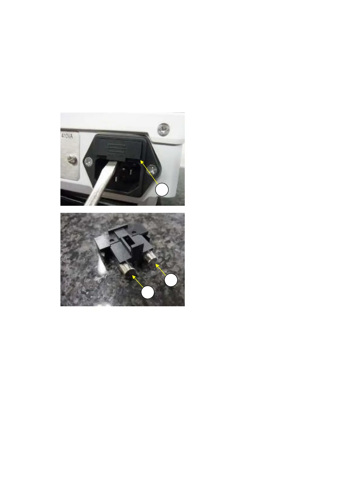
1) Remove the fuse holder by inserting a flat head screwdriver below inside the filter (B11) fuse holder
(Fig. 8).
Remove the two fuses (S18) from the fuse holder (Fig. 9).
Install two new fuses (S18) by reversing steps 1 and 2 above.
2)
3)
B11
S18
S18
Fig. 8
Fig. 9
2.3.2
e
l
cing the M
in Bo
d Assembl
B2)
1) Disassemble the balance down to the case assembly (S2) by following the procedure in 2.2
Removing the Case.
2) Remove the three P4 M4
×
8 screws (B53) that fasten the main board assembly (B2) (Fig. 10).
16 DBS-SH-e-1210