2.3.
e
l
cing the F
ce C
il Assembl
L1)
1) Remove the DBS unit assembly (1) using the same procedure as described in 2.3.6 Replacing the
DBS Unit Assembly (U1).
Remove the solder on the lever assembly (U7) side of the two Pt-Ni bands (U17).
Note: Do not break or scratch the Pt-Ni bands (U17).
Loosen and remove the two P3 M3
×
15 socket head bolts (U58) that fasten the detector frame (U10)
(Fig. 28).
Loosen the four M2.5
×
6 (U54) screws that fasten the four magnetic lids (U16), and remove the
magnetic lids (U16) by sliding them out to the side (Fig. 29).
2)
3)
4)
U16
U10
U
4
Fig. 28
Fig. 29
5)
Remove the four P3 M3
×
15 socket head bolts (58) that fasten the lever assembly (U7), and remove
the lever assembly (U7) from the top.
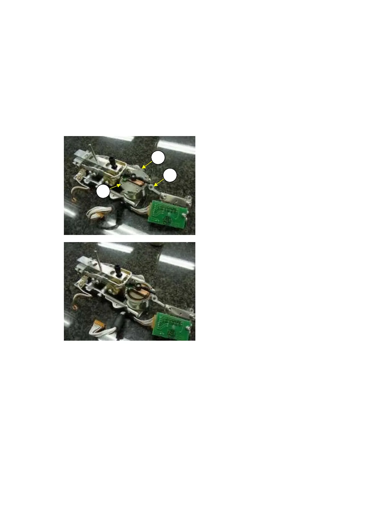
Unsolder the twisted wire (L7) from the terminal plate on the force coil assembly (L1).
Loosen and remove the M2.5
×
6 screws (L5) and M2.6 PB SPG washers (L6) used to fasten the
force coil assembly (L1).
Tentatively fasten the new force coil assembly (L1) to the lever assembly (U7) using the M2.5
×
6
screws (L5) and solder the twisted wires (L7) to the force coil assembly (1) (Fig. 30).
Note: The yellow wire is on the left and the blue wire on the right, as viewed from where the
lever assembly (U7) is attached.
Insert the lever assembly (U7) from the top of the unit and tentatively fasten it with four P3 M3
×
15
socket bolts (58).
6)
7)
8)
9)
10) The stopper plate (U14) and the lever stopper (U15) are attached to the detector frame (U10). Pass
the pin on the lever assembly (U7) through the pin hole in the stopper plate (U14) and pass the
24 DBS-SH-e-1210