.2 Ad
usting the
ilt E
1) Disassemble the balance down to the case assembly (S2) by following the procedure in 2.2
Removing the Case.
Level the balance by turning the two level adjusters (B6) at the front of the balance so that the bubble
in the level gauge is centered.
Place the sample pan and pan supporter assembly (S11) in position and supply power by connecting
the power cord.
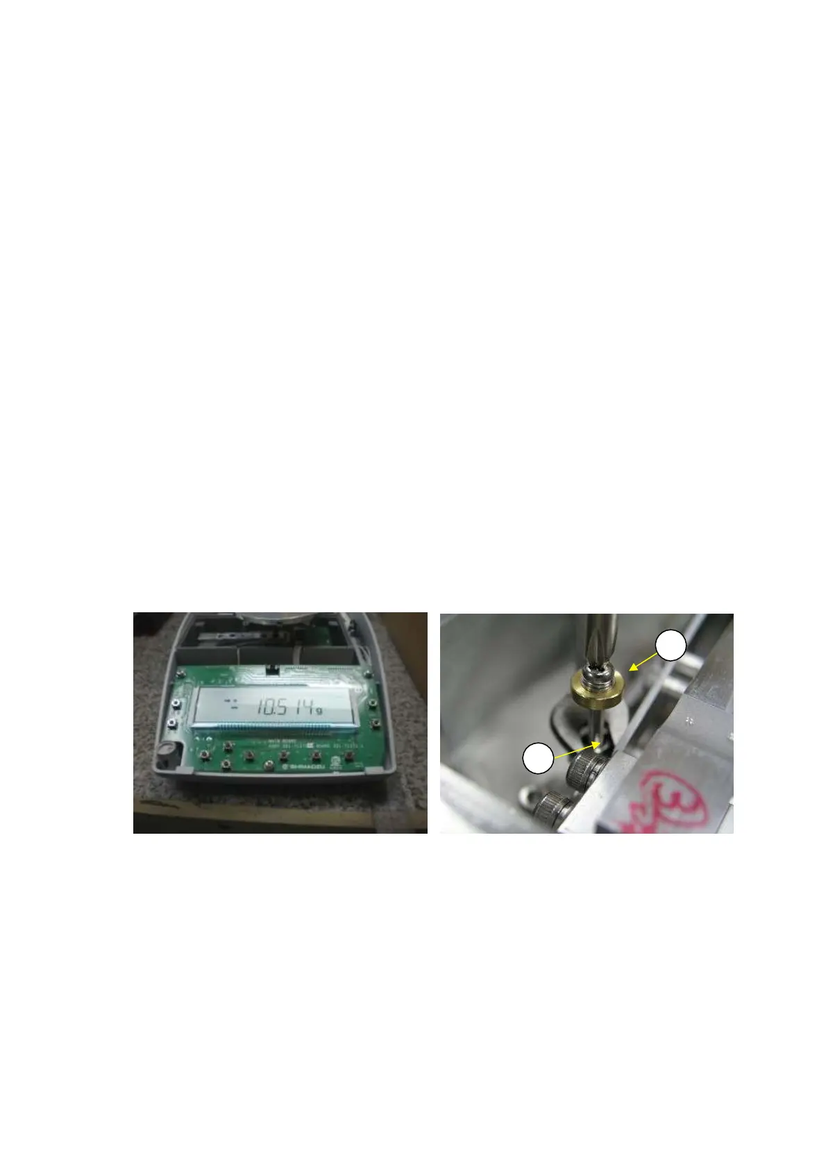
Press the Power key to display grams, insert a 1 mm thick shim in one location, under the front right
foot of the balance, and then read the display value (Fig. 62).
If the displayed value is outside adjustment standards, unplug the AC adapter, insert the lever
positioning pin (J1) into the lever fastener hole on the top of the OPF, up to the reference line, and
then loosen the M3 nut (L9).
If a positive value is displayed, turn the P4 M3
×
25 screw (L12) clockwise on the lever assembly (U7).
If a negative value is displayed, turn it counterclockwise.
Pull out the lever positioning pin (J1) and supply power by plugging in the power cord.
Repeat steps 4 to 7 to make adjustments. When finished making adjustments, use the M3 nut (L9) to
lock the P4 M3
×
25 screw (L12) (Fig. 63).
2)
3)
4)
5)
6)
7)
8)
N
te: Be su
e to unplug the AC ada
te
and le
ethele
e
positioning pin
J1) inse
ted into
the OPF when adjusting the screw and nut on the lever assembly (U7).
N
te: If tilt e
d
ustments we
e not necess
tthef
ct
, a weight
U10) m
n
t
e
attached to the lever assembly (U7).
L12
9
Fig. 62 Fig. 63
DBS-SH-e-1210 43