.3 Ad
usting the C
ne
lo
d E
N
te:
nl
d
ust c
nerlo
d e
f
min
er
o
le
els (m
x.
0 count).
For larger errors, replace the entire TX unit assembly (1).
1) Disassemble the balance down to the case assembly (S2) by following the procedure in 2.2
Removing the Case.
Level the balance by turning the two level adjusters (B6) at the front of the balance so that the bubble in the
level gauge is centered.
Place the sample pan and pan supporter assembly (S11) in position and supply power by plugging in the
power cord.
Press a key to display grams.
Place the following calibration weight on the sample pan and press the
[TARE]
key to display "0 g."
2)
3)
4)
5)
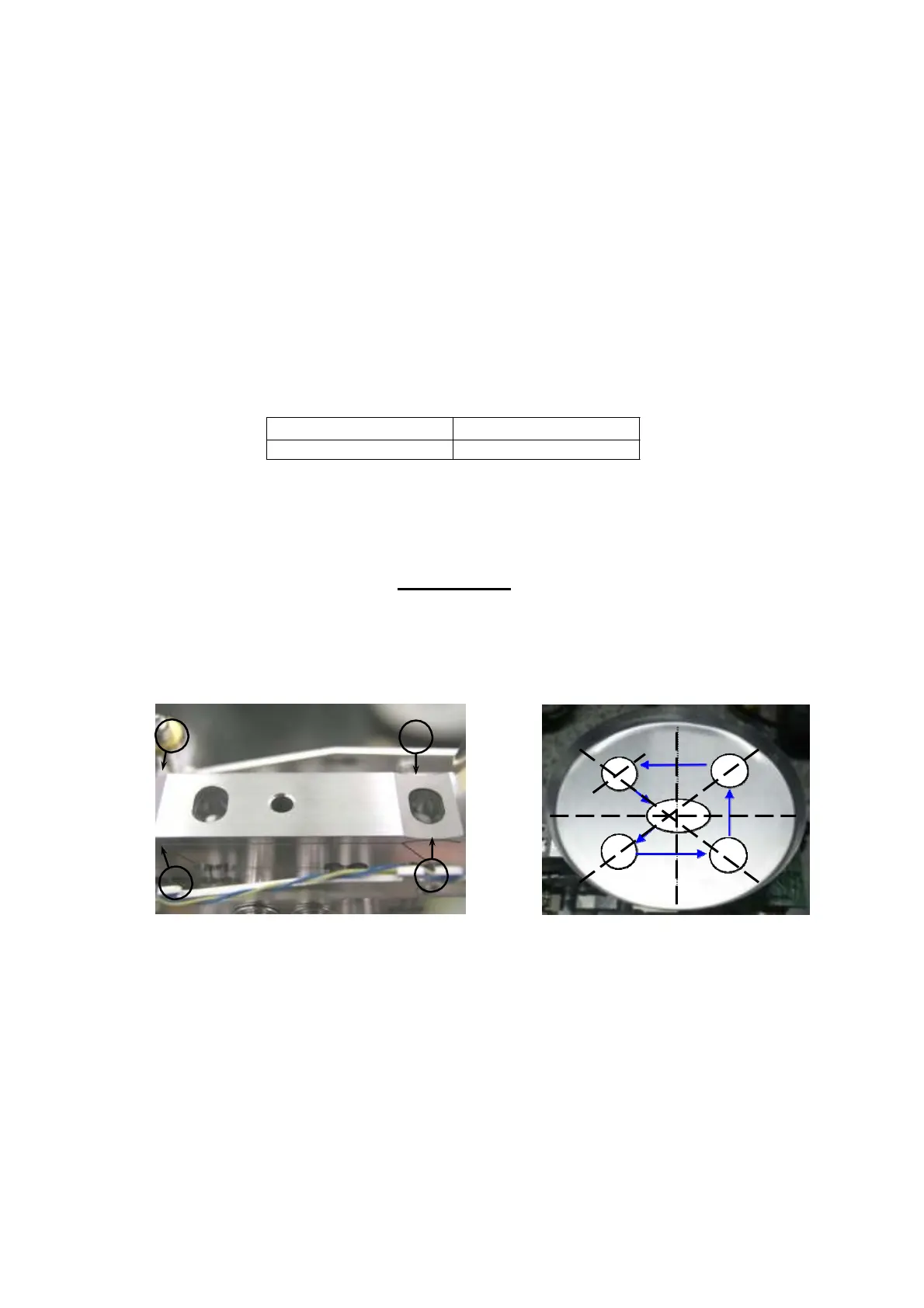
6) Record the indicated value for each position indicated in Figure 65 by placing and measuring the
weight successively in the center (1), then off-center positions (2), (3), (4), and (5), and, lastly, in the
center (1) again.
Use the cornerload adjustment tools (J3 and J4) to cut metal from the thin part of the parallel guide
corresponding to the position where a positive value
was displayed (Fig. 64).
7)
8) Repeat steps 6 and 7 to record display values and make adjustments until the values are within the
adjustment standards.
5
4
1
3
2
Fig. 64 Fig. 65
5
4
2
3
Model Weight
DBS 60-3 30 (g)
44 DBS-SH-e-1210