2.3.1
e
l
cing the DBS He
te
S
)
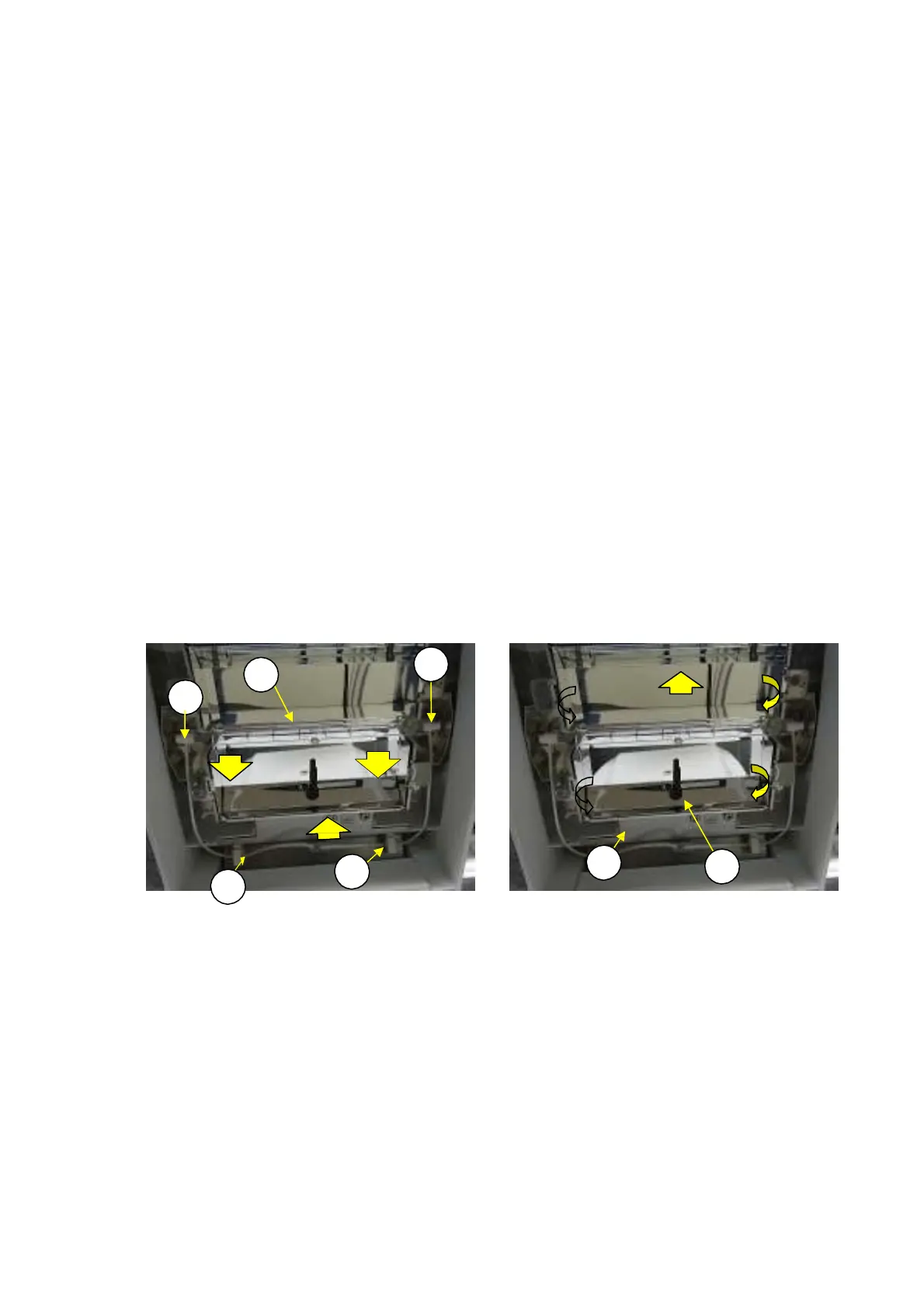
1) Remove the glass unit assembly (3) using the same procedure as described in 2.3.10 Replacing the
Glass Unit Assembly (S3).
Disconnect the heater (S5) connector and remove the wire from the wire saddle (H12).
Holding the heater (S5) insulator, pull it toward the front to remove the heater (S5) from the heater
bracket (H4) (Fig. 39).
Reassemble by reversing steps 1 to 4 above.
Note: Do not touch the glass portion of the heater (S5). Doing so could shorten the service
life of the heater.
2)
3)
4)
2.3.1
e
l
cing the
eflecto
Pl
te
H
)
1) Remove the glass unit assembly (3) and heater (S5) using the same procedure as described in
2.3.13 Replacing the DBS Heater (S5).
Slightly bend the reflector plate (H9) inward and unhook the flanges in the four corners from the
heater frame (H3) (Fig. 40).
Remove the thermistor (H10) from its hole by sliding it toward the front, and remove the reflector
plate (H9).
Reassemble by reversing steps 1 to 3 above.
2)
3)
4)
N
te: Befo
e inst
lling the
eflect
pl
te
H
),
emo
e onl
the p
tecti
e film
n the flanges.
After installation, peel off the rest of the film, being careful to not leave any finger
prints.
1)
H4
1)
S5
2)
H4
H9
2)
2)
1)
1)
1)
H3
H10
H12
H12
Fig. 39 Fig. 40
DBS-SH-e-1210 29