B
3
B2
B
3
B
3
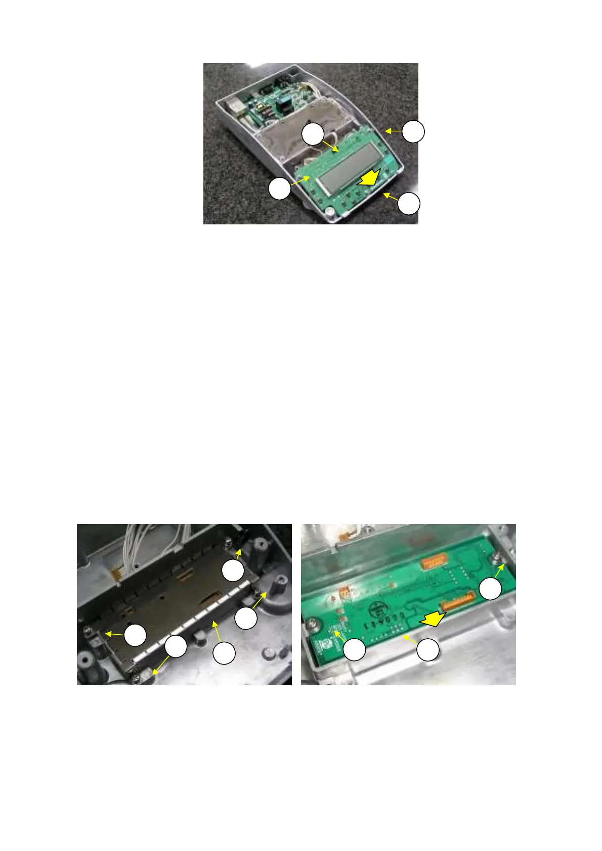
Fig. 10
Disconnect the three cables from connectors J1, J2, and J4 on the main board assembly (B2)and
separate from base assembly.
Remove the two EEMPROM from its socket on the back of the main board assembly (B2), being
careful not to damage its pins.
3)
4)
M4: Moisuture analyzer’s memory function M5: Balance’s fixed information
5)
6)
Install the EEPROM on the same place of the new main board assembly (B2).
Install the new main board assembly (B2) by reversing steps 2 to 6 above.
N
te: When assembling, inst
ll the m
in b
d ass
(B2) setting f
nt side
f
the base assy(B1)
2.3.
e
l
cing the An
l
g Bo
d Assem
l
B3)
1) Disassemble the balance down to the main board assembly (B2), in the same manner as described
in 2.3.2. Replacing the Main Board Assembly (B2), steps 1 to 3.
Disconnect the three cables from connectors J1, J2, and J3 on the analog board assembly (B3),
loosen the four P4 M4
×
8 screws (53)and then remove the analog board cover plate (B14) (Fig. 11).
Loosen and remove the two P4 M4
×
8 screws (B22) that fasten the analog board assembly (B3)
Fi
. 12
.
2)
3)
B
3
B22
B
3
B
3
B
3
B22
B3
B14
Fig. 11 Fig. 12
4) Install a new analog board assembly (B3) by reversing steps 2 and 3 above.
Note: When assembling, install the analog board assy(B3) setting front side of
the base assy(B1) (Fig.12)
N
te: When assemblin
, use cli
CS-5
B2
to secu
el
hold the
we
bo
d assembl
B
DBS-SH-e-1210 17