7) Install a new power board assembly (B4) by reversing steps 1 to 5 above.
N
te: When assembling, use clip CS-5
B2
) to secu
el
hold the p
we
bo
d assembl
B
)
cable down toward the bottom (Fig. 18).
Note: When assembling, tighten screws of procedure 5 temporally and tighten firm after
ti
htenin
sc
ew
f
ocedu
e2and3.
B26
B4
Fig. 18
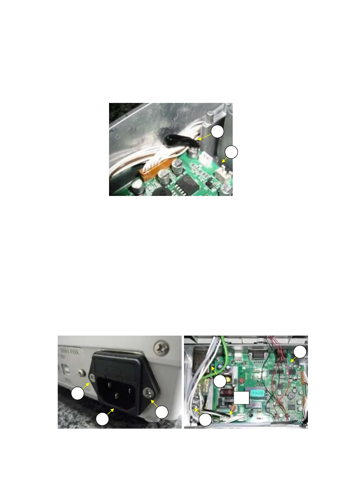
2.3.
e
l
cing the Inlet
ssembl
S11)
1) Disassemble the balance down to the case assembly (S2) by following the procedure in 2.2
Removing the case.
Loosen the two screws,pan head M3x8(B52) that fasten the inlet assembly(S11).(Fig.19)
Disconnect the cables connected to the J1 connector of the power board assembly(B4),(Fig.20)
Loosen the screw P4 M4x8(B53)(Fig.20)
Remove the inlet assembly(S11) from rear side of the base assembly(B2)
Install a new inlet assembly (S11) by reversing steps 1 and 5 above.
2)
3)
4)
5)
6)
N
te: When assembling, inst
ll the inlet
ssem
l
(S11)
inted face t
p.
Fig.19, 20)
Note: When assembling, align the cables of the inlet assembly (S11) as shown. (Fig.20)
B4
11
B
2
B
2
11
B
3
Fig.19 Fig.20
J1
20 DBS-SH-e-1210