2.3.1
e
l
cing the F
nC
ble Assembl
C
)
1) Disassemble the balance down to the case assembly (S2) by following the procedure in 2.2
Removing the Case.
Lay down cushioning materials to prevent scratching, and invert the case assembly (S2).
On the front side, secure the top base (C3) and window panel (C7) with tape. On the rear side, inser
a shim about from 0.8 to 1.5 mm thick between the top base (C3) and top case (H1) (Fig. 42).
Remove the four 4
×
12 self-tapping screws (C52), pull out each cable from the hole in the case
assembly (S2) to separate it from the top case (3) (Fig. 41).
2)
3)
4)
C7
C
2
C
2
C3
C
2
H1
C
2
Fig. 41
Fig. 42
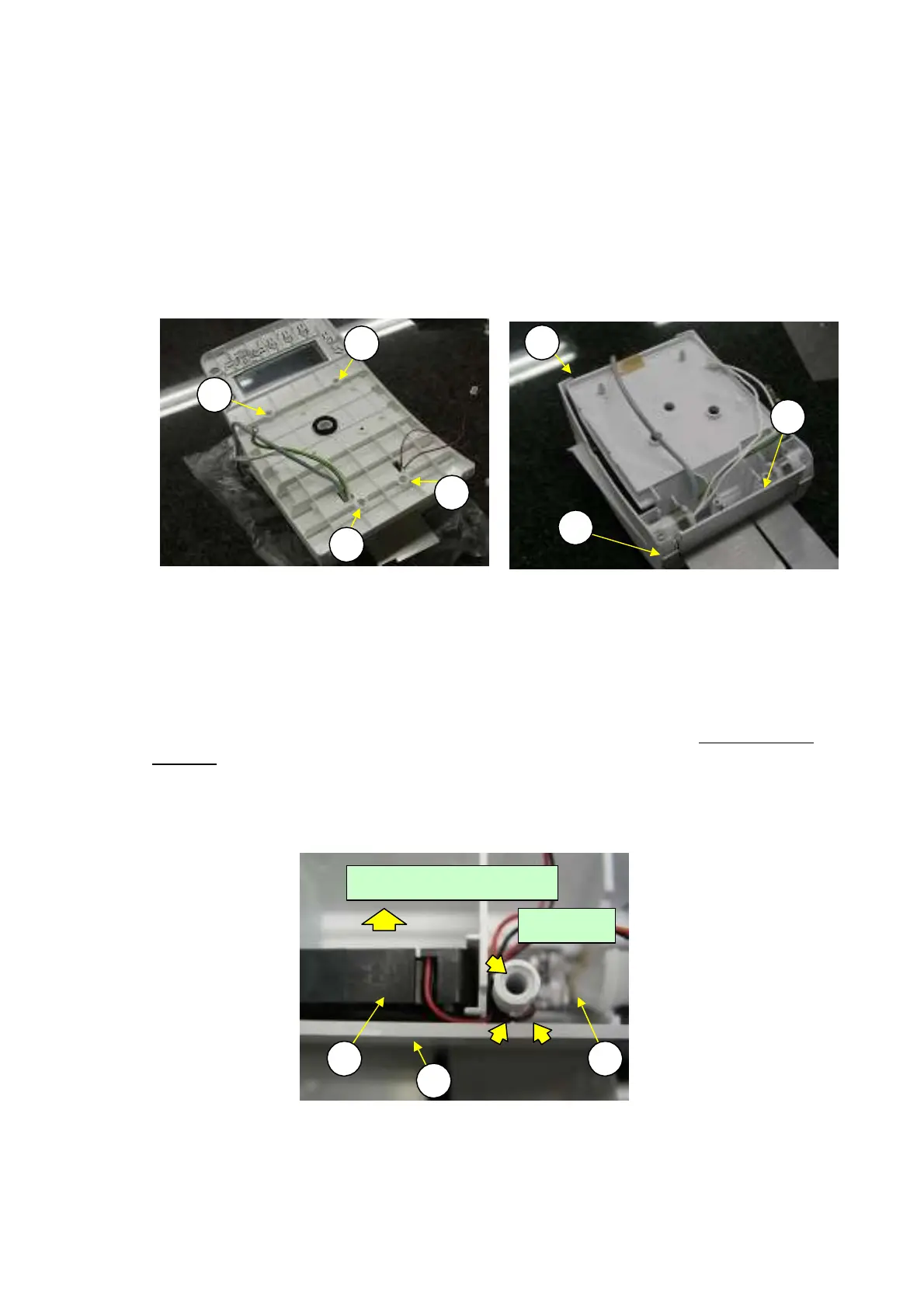
5)
6)
Pull the fan cable assembly (C5) out from the top base (C3) frame.
Insert the new fan cable assembly (C5) into the top base (C3) frame (Fig. 43).
Note: Insert the fan cable assembly so that the arrow, molded into the assembly, is oriented
in the direction shown below.
Insert the wires from the fan cable assembly (C5) and LSW cable assembly (C6) into the slit in the
7)
Top base
(C3) (Fig. 43).
8) Reassemble by reversing steps 1 to 4 above.
Note: Make sure no wires are pinched between the case assembly (S2) and top base (C3).
Fig. 43
C5 C6
C3
Slits
Discharge Direction
30 DBS-SH-e-1210