2.
Disassembling
and
ssembling
the Balance
2.1 P
ec
utions
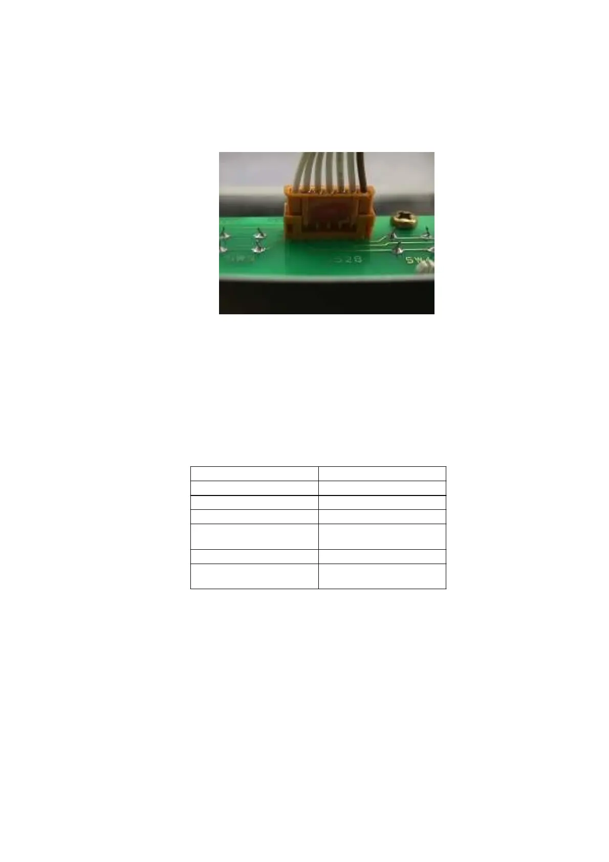
1) Pull connectors straight out when disconnecting. Never pull them out at an angle.
* Pulling connect
s out
t
nanglec
uld bend the te
min
l
ins, m
king it difficult to
re-insert the connector.
Fig. 1
2) Before disassembling or assembling the MOC unit assembly (1) related parts, insert the lever
positioning pin (J1) into the lever fastener hole on the top of the OPF, up to the reference line.
Note: Insert the pin while slightly lifting up the lever assembly (U7). Be careful not to damage
the elastic support.
3) Use a controlled torque driver to tighten the screws to the torques shown in the table below.
(*1) 80 [cN• m] for only the sensor shaft
4) To retighten self-tapping screws, carefully align the threads so they are not damaged.
Note: Turn the screw counterclockwise until it drops back into the screw hole, and screw it in
to tighten.
Screw Torque [cN•m]
M2 10
M2.5 25
M3 pan head 90
M3 hexagonal socket
head bolt
150
M4 pan head 180
M4 hexagonal socket
head bolt
300 (*1)
12 DBS-SH-e-1210