.1 Ad
usting the Detect
Assembl
U11) Height
1) With the connector on the ILS 2S-90 cable (U20) that is connected the analog board assembly (B3)
disconnected, plug in the power cord to provide power.
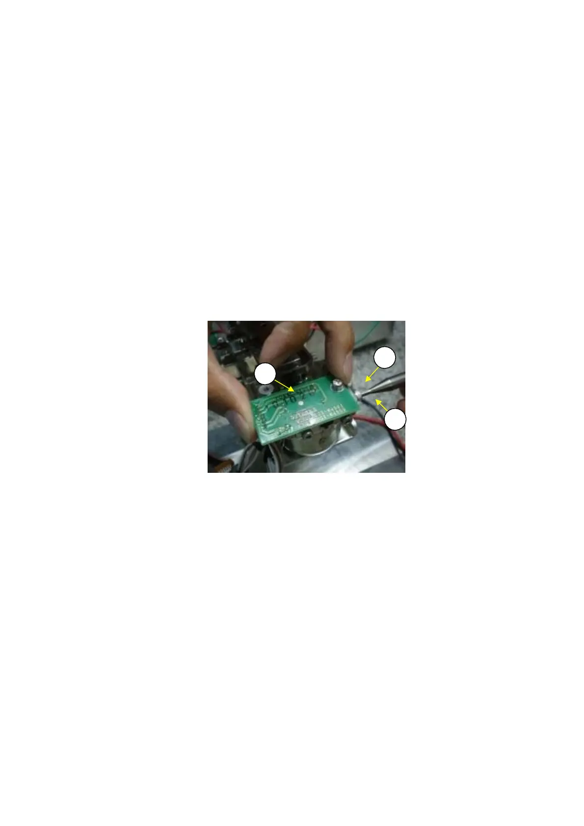
Connect electrical tester terminals to the TP1 (+) and TPG (-) pins on the analog board assembly
(B3).
With the P3 M3
×
10 socket head bolts (U53) on the detector assembly (U11) slightly loosened, lightly
move the lever assembly (U7) up and down until it hits the lever stopper (U15), and adjust the detector
assembly (U11) height so that (+) is inverted to (-) on the tester display and the difference between the
(+) and (-) values does not exceed 25 %.
Note: If the display on the digital multimeter remains "(-)(-)," lower the detector assembly (U11)
height. If it remains "(+)(+)," raise the detector assembly (U11) height.
2)
3)
4)
5)
6)
After making adjustments, fasten the P3 M3
×
10 socket head bolt (U53) (Fig. 61).
Disconnect the electrical tester TP1 and TPG pins from the analog board assembly (B3).
Temporarily unplug the AC adapter, and connect the ILS 2S-90 cable (U20) connector to the analog
board assembly (B3).
U
3
U11
U
3
Fig. 61
42 DBS-SH-e-1210