2.3.1
e
l
cing the
ight Hinge
H13), Left Hinge
H1
), and Hinge
ings
H1
)
1) Separate the case assembly (S2) and heater case assembly (C1) by following the procedure in
2.3.15 Replacing the Fan Cable Assembly (C5).
Separate the LSW cable assembly (C6) by following the procedure in 2.3.16 Replacing the LSW
Cable Assembly (C6)
Secure the front side with tape, remove the shim from the rear side, and then rotate the top base
(C3) about 135 degrees toward the rear to separate it from the heater case assembly (C1).
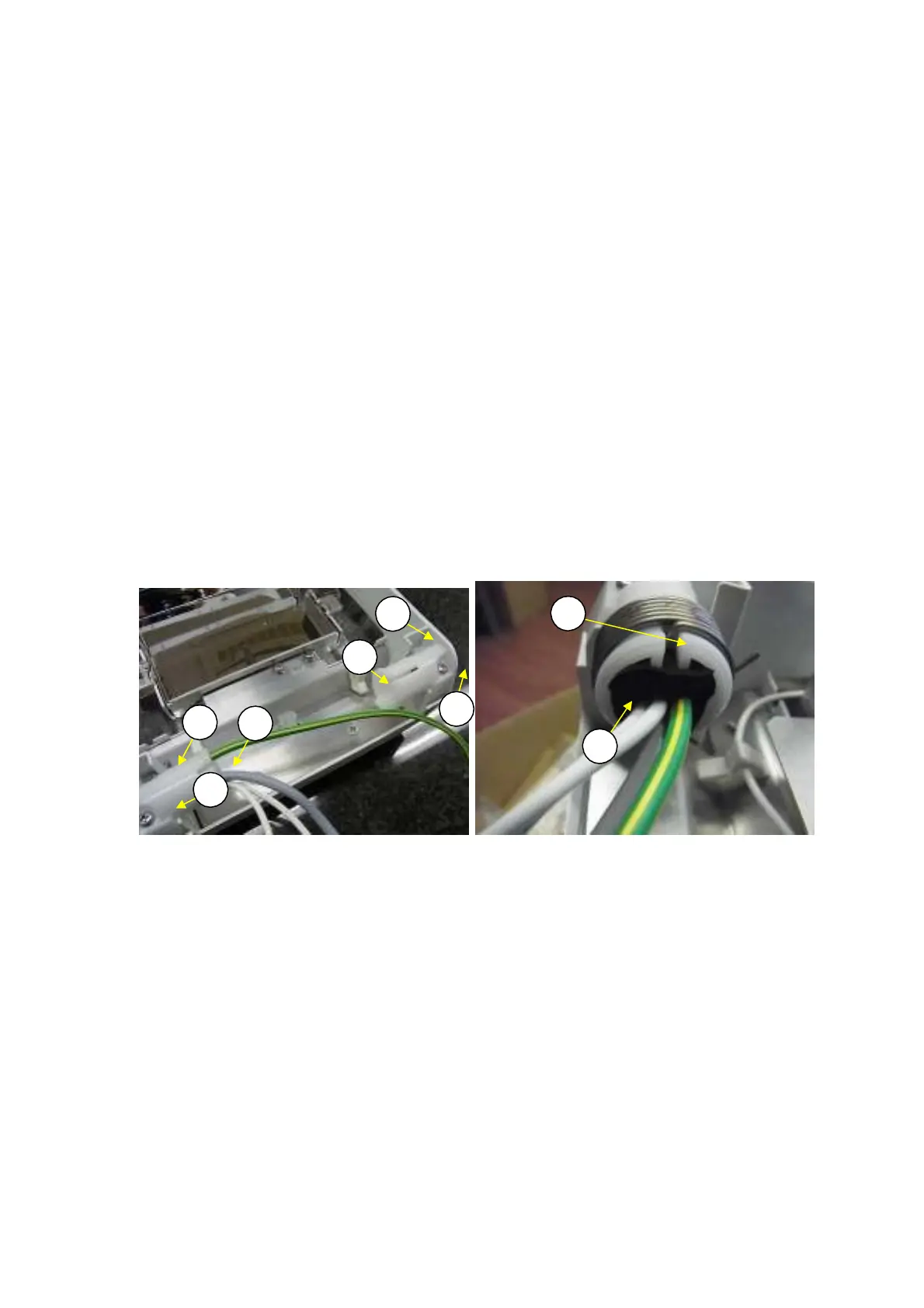
Remove the hinge springs (H15) from the right hinge (H13) and left hinge (H14) (Fig. 46).
Loosen the two 4
×
12 self-tapping screws (H60) on each hinge, pull out the three cables from the
right hinge (H13), and then remove the right hinge (H13) and left hinge (H14).
Pass the three cables through the right hinge (H13) prior to big one, align the inside flange spacing
on both hinges with the spacing of the bearings on the top base (C5), and then fasten the new right
hinge (H13) and left hinge (H14) with the two 4
×
12 self-tapping screws (H60) each.
Reattach the tubing (H24) to the inner hooks on the new hinge springs (H15) and insert the springs
through the right hinge (H13) and left hinge (H14).
Note: Cover the inner end of the hinge spring(H15) with the tubing (H24) or the rubber
sponge(H25) not to touch the cables. In some case, there is no tubing(H24) originally.
Pass the three cables through the rubber sponge(H25) and insert it in the left hinge(H14) to align with
the end of the left hinge(H14)(Fig.47)
2)
3)
4)
5)
6)
7)
8)
H
0
H24
H13
H
0
H
0
H14
H25
H
0
Fig. 46 Fig. 47
32 DBS-SH-e-1210