9) Starting with the top base (C3) rotated toward the rear about 135 degrees and the outer hooks on
both hinge springs (H15) hooked to the spring retention groove on the top base (C3)(Fig.48), rotate
the top base (C3) toward the front holding the hinge R(H13) and the hinge L(H14) upward without
gap against the hinge guide of the top base(C3) upward(Fig. 49).
10) On the front side, secure the top base (C3) and window panel (C7) with tape. On the rear side, insert
a shim about 1 mm thick between the top base (C3) and top case (H1) (Fig. 42).
11) Reassemble by reversing steps described in 2.3.16 Replacing the LSW Cable Assembly (C6).
12) Reassemble by reversing steps described in 2.3.15 Replacing the Fan Cable Assembly (C5).
13) When replacing the right hinge (H13) or left hinge (H14), confirm that the LSW functions properly
when it is assembled with the case assembly (S2), by opening and closing the heater cover.
Note: Confirm the LSW functions properly in the following modes.
1. Close slowly.
⇒
If it does not function properly, retighten LSW screws or replace LSW.
2. Close while pressing laterally on heater cover (Fig. 45). ⇒ Move LSW closer to hinges and
retighten.
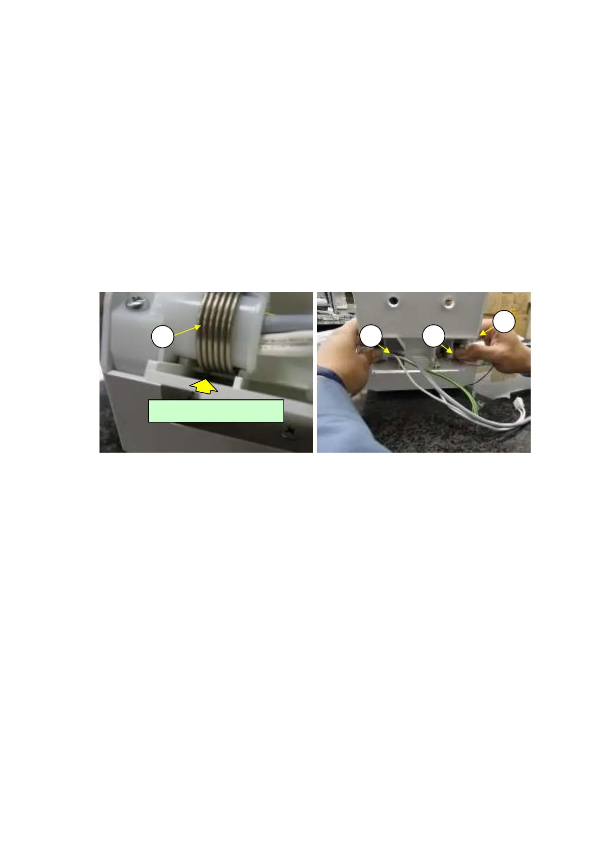
C3
H14 H13
H15
Fig. 48 Fig. 49
Pocket for spring hook
DBS-SH-e-1210 33