2.3.
e
l
cing the P
we
Bo
d Assembl
B
)
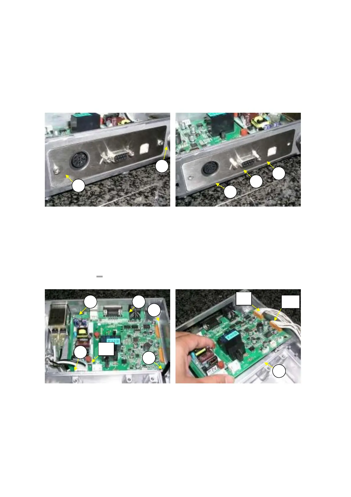
1) Disassemble the balance down to the case assembly (S2) by following the procedure in 2.2
Removing the case.
Loosen the two M3
×
6 bind screws (B55) (Fig. 14).
Remove the two D-sub screws (B25) that fasten the power board assembly (B4) and rear panel (B5),
and remove the rear panel (Fig. 15).
2)
3)
B
5
B25
B25
B
5
B5
Fig. 14 Fig. 15
4)
5)
Disconnect J1l cables connected to the power board assembly (B4) (Fig. 16).
Loosen the four P4 M4
×
8 screws (B53) that fasten the power board assembly (B4), and remove the
board along with clip CS-5 (B26) (Fig. 16).
Note: The power board assembly (B4) can be removed by lifting it up at an angle, as shown
in Fig. 17
.
Disconnect J9 and J10 cables connected to the power board assembly (B4) (Fig.17)
6)
B
3 B4
B
3
B
3
B
3
B4
Fig. 16 Fig. 17
J1
J10
J9
DBS-SH-e-1210 19