2.3.1
e
l
cing the Therm
l Fuse
H
)
1)
2)
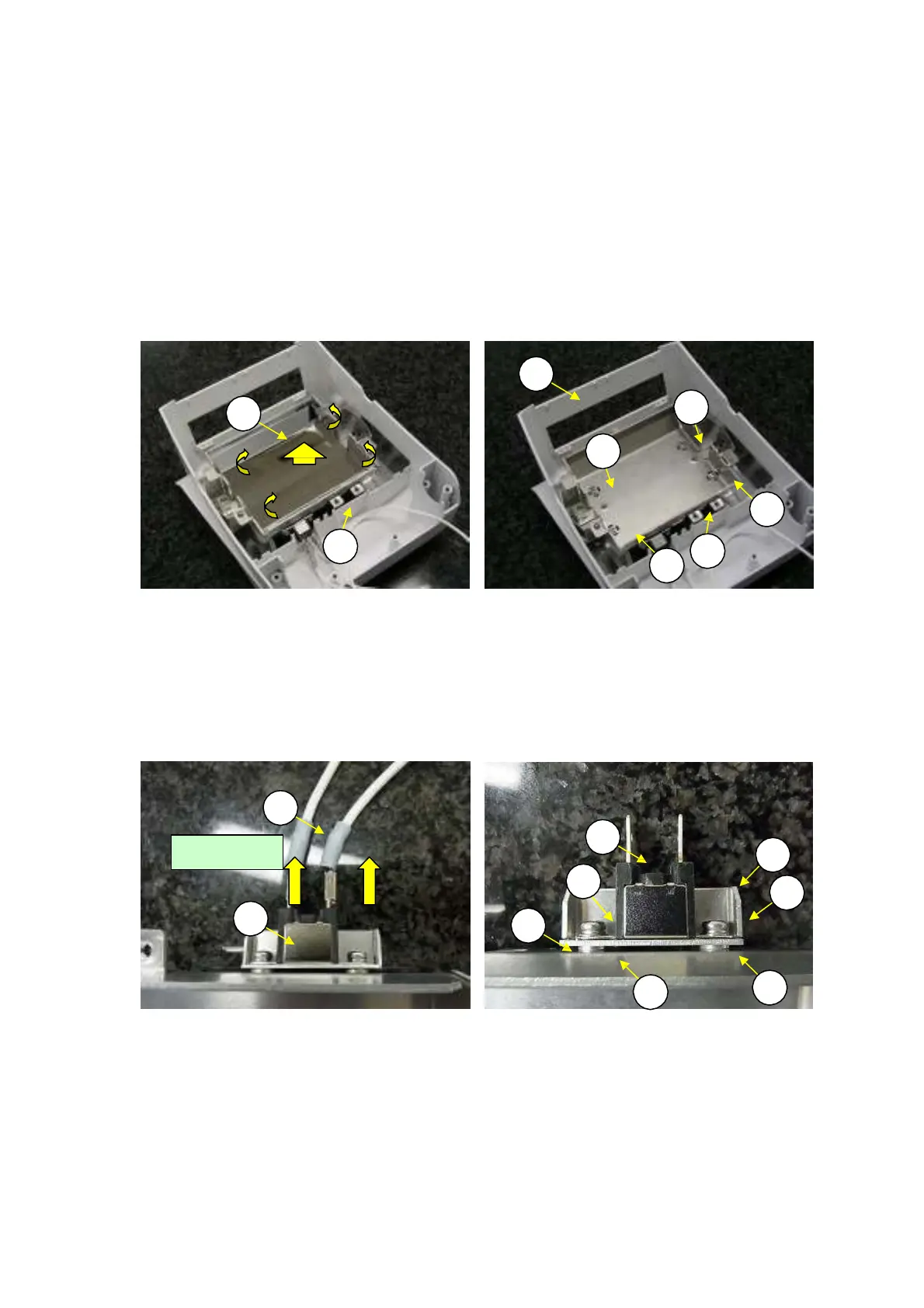
Remove the thermistor by following the procedure in 2.3.18 Replacing the Thermistor (H10).
Remove the reflector plate (H9) by unhooking the flanges in the four corners from the heater frame
and slightly bending the reflector plate (H9) inward (Fig. 56).
Note: Be careful not to get finger prints on the reflector plate.
Loosen the four 3
×
10 self-tapping screws (H55) and remove the heater frame (H3) from the top case
(H1) (Fig. 57).
3)
H1
1)
H
5
H9
2)
1)
H
5
1)
H
5
1)
H3
H3
H
5
Fig. 56 Fig. 57
4)
5)
Pull out the Faston terminals on the heater junction cables (H7) from the thermal fuse (H6) (Fig. 58).
Loosen the two P4 M3
×
8 screws (H61) and remove the two spacers (H16), plate thermal fuse (H17),
and thermal fuse (H6) from the heater frame (H3) (Fig. 59).
Reassemble by reversing steps 1 to 5 above.
6)
H7
H6
H17
H
1
H
1
H6
H3
H16
H16
Fig. 58 Fig. 59
Short
c
a
b
l
e
36 DBS-SH-e-1210