4)
5)
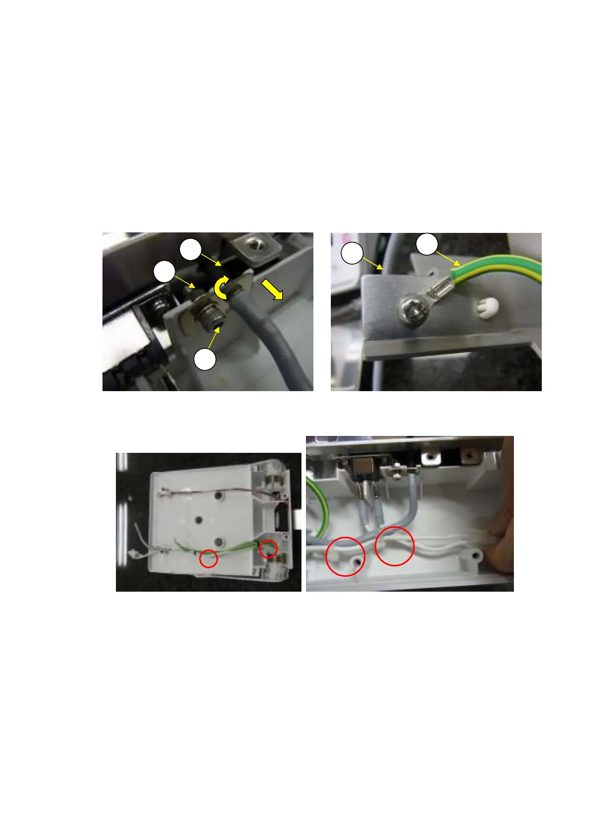
Cut the Cable tie,T18S-HSW(H26) bundled the Cables by the nipper (Fig. 54,55)
The thermistor (H10) can be removed by loosening the M3 flange nuts (H56) and P3 M3
×
10 socket
head bolts (H57) partway, rotating the thermistor clockwise 90 degrees, and then sliding it to the rear
(Fig. 52).
Bundle the Cables with the Cable,tie,T18S-HSW(H26) as shown in Fig.54 and Fig.55) then,
Reassemble by reversing steps 1 to 4 above to take care not to sandwich the cables between assembled
parts.
Note: Be careful not to damage the black heat resistant paint of 10mm from the end when
inserting the thermistor (H10) into the hole.
Note: Tighten theFG earth cable (H17) as shown to be behind the blind cover (H11). (Fig.53)
6)
H10
H
6
1)
2)
H
7
Fig. 52
Fig. 54 Fig.55
DBS-SH-e-1210 35
H11
Fig.53
H7
H17