2.3.
e
l
cing the Sens
sh
ft
U
)
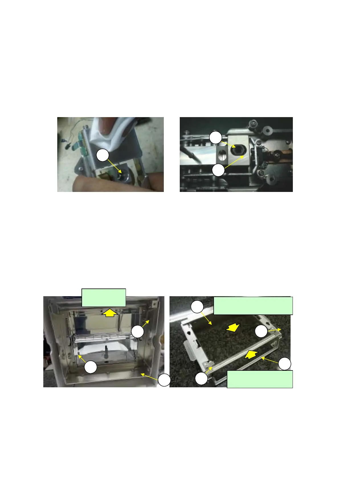
1) Remove the DBS unit Assembly (U1) using the same procedure as described in 2.3.6 Replacing the
DBS Unit Assembly (U1).
Loosen the P4 M4
×
14 socket head bolt (U59) that fasten the sonsor shaft (U4) and remove(Fig.33).
Install a new sensor shaft (U4) by using a pan support positioning jig (J9) to position the sensor shaft
and fasten by the P4 M4
×
14 socket head bolt (U59)(Fig.34).
2)
3)
N
te:
Tighten torque for the Sensor shaft(U4) : 80[cm・N].
J9
U
9
U4
Fig.33 Fig.34
2.3.10
e
l
cing the Glass Unit Assembl
S3)
1)
2)
With the heater cover open, loosen the two P4 M3
×
16 socket head bolts (H51) (Fig. 35).
Slide the glass unit assembly (S3) upward and remove it from the heater cover by pulling the P4
M3
×
16 socket head bolts (H51) out through the wide part of the pear-shaped holes.
Loosen the P4 M3
×
6 screws (G51) and remove the two glass springs (G3) (Fig. 36).
The main glass (G4) and front glass (G5) can be removed by sliding them out of the glass holder
assembly (G1).
Reassemble by reversing steps 1 to 4 above.
3)
4)
5)
G4
H
1
G
1
G5
H
1
G
1
S3
Fig. 35 Fig. 36
2.3.11
e
l
cing the
ind
w P
nel
C
)
1) Remove the glass unit assembly (3) using the same procedure as described in 2.3.10 Replacing the
Glass Unit Assembly (S3).
Slide the
front
glass in
this
direction.
Slide the
main
glass in this
direction.
Slide in this
direction.
DBS-SH-e-1210 27