protruding part of the lever assembly (U7) through the slit in the lever stopper (U15) at the same time.
Tentatively fasten the detector frame (U7) with two P3 M3
×
15 socket head bolts (58).
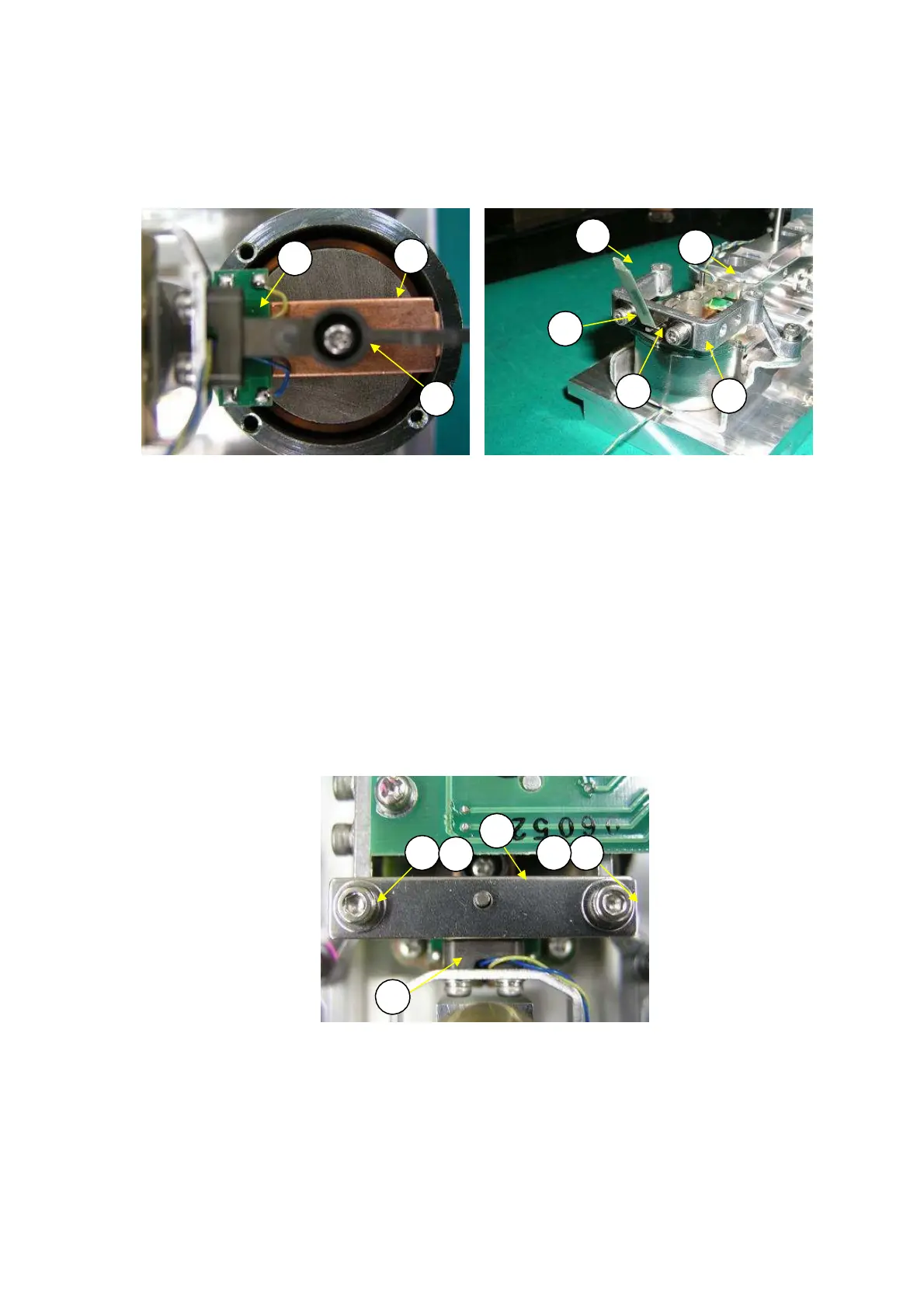
11) Insert and position a gap setting shim (J3) between the bottom of the lever shutter on the end of the
lever assembly (U7) and the bottom of the slit in the lever stopper (U15), and fasten it with four P3
M3
×
15 socket head bolts (58) (Fig. 31).
J3
U7
1
U7
8
U15
8
5
Fig. 30 Fig. 31
12) Remove the tentatively fastened detector frame (U7).
13) Viewing the DBS unit assembly (U1) from above, fasten the force coil assembly (L1) with the center
of the magnet assembly (U9) and force coil assembly (L1) aligned.
14) Install the four magnetic lids (U16) by sliding them in from the side and fasten them with the four
M2.5
×
6 screws (U54).
15) Again, pass the pin on the lever assembly (U7) through the pin hole in the stopper plate (U14) and
pass the protruding part of the lever assembly (U7) through the slit in the lever stopper (U15) at the
same time. Fasten the detector frame (U10) with the two P3 M3
×
15 socket head bolts (58).
16) Solder the two Pt-Ni bands (U17) to the lever assembly (U7).
Note: Make sure the Pt-Ni bands do not twist or bend during soldering.
17) Align the hole in the stopper plate (U14) with the pin on the lever assembly (U7), and fasten it with an
M
×
6 soc
t head b
lt
U
and M3
ashe
U5
Fi
.
2
.
U14
U
7 U
7 U
6
U
6
U7
Fig. 32
18) Pull out the lever positioning pin (J1) from the MOC unit assembly (U1) and try lightly wiggling the
DBS unit assembly (U1). If the lever assembly (U7) moves up and down smoothly and the lever
stopper (U15) emits a clear contact sound, the DBS unit assembly (U1) assembly process is finished.
19) Install a new DBS unit assembly (U1) by reversing steps 4 to 6 in 2.3.6 Replacing the DBS Unit
Assembly (U1).
DBS-SH-e-1210 25