kewtechcorp.com
9
kewtechcorp.com
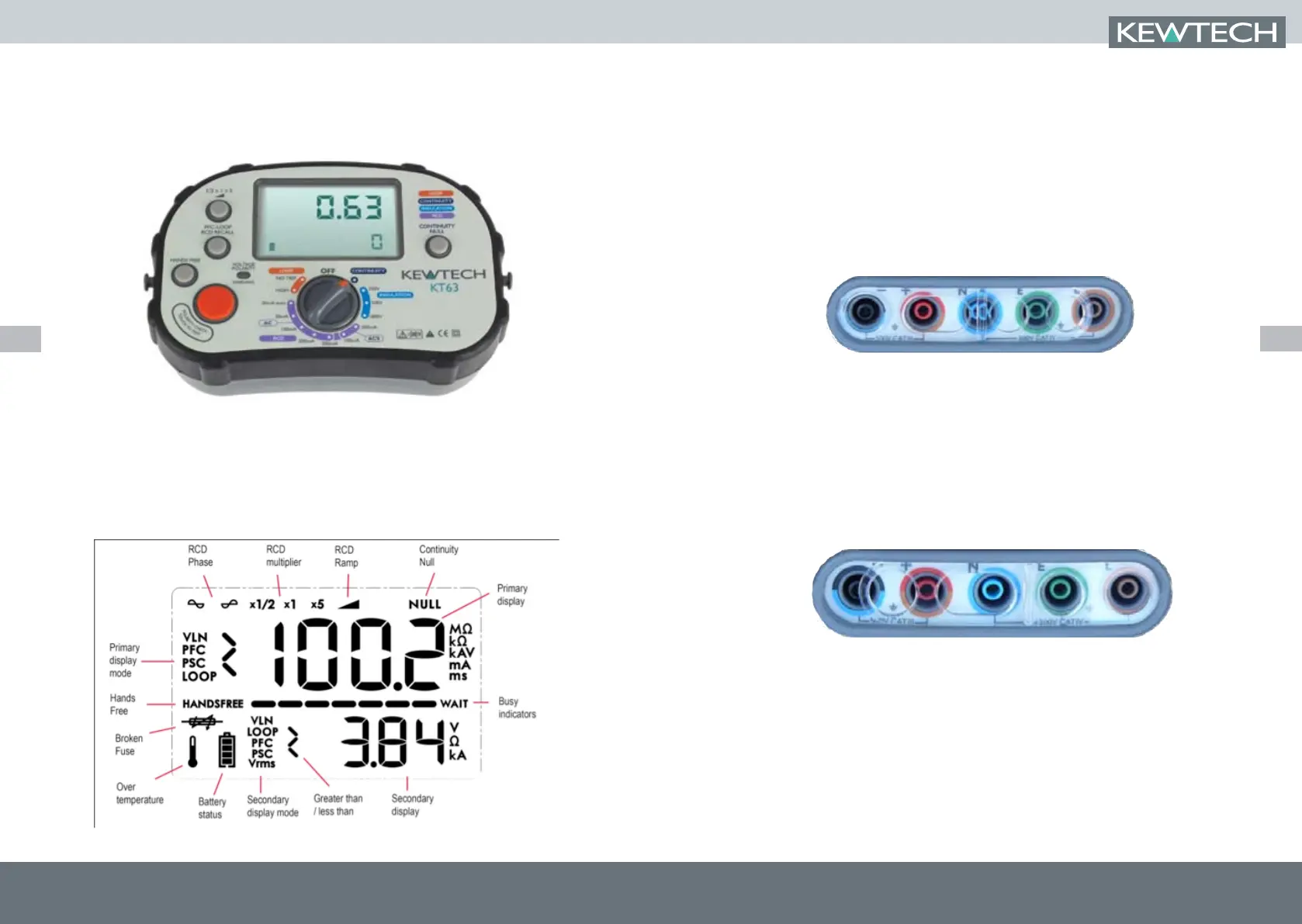
Overview of the switches and LCD
The Primary display of the large LCD shows the result of the test being conducted. At the
same time a secondary display area shows supporting information e.g. for an insulation test
the main display shows the resistance of the insulation whilst the secondary display confirms
the test voltage applied.
Test lead inputs
The test lead input/ output terminals are separated into two groups by the clear sliding
interlock cover.
When slid to the left (figure 1) the interlock cover exposes only the Blue/Black terminal
(marked -) and the Brown/Red terminal (marked +). These are used for the Continuity and
Insulation test functions.
For both of these functions two of the test leads from the ACC063 set are used. The Brown
4mm Plug should be connected to the Brown/Red socket (+) and the Blue 4mm plug
connected to the Black/Blue socket (-)
Fig.1 Interlock in position for Continuity and Insulation testing
Moving the interlock cover to the right (figure 2) blanks off these inputs and exposes the
Blue (Neutral), Green (Earth) and Brown (Line) inputs that are used for Loop and RCD testing.
This allows for connection of either the 13A mains lead (KAMP12) or the 3-pole test lead set
ACC063 for the live testing functions.
When using these lead sets the Brown 4mm plug is connected to the Brown/Red socket
(L), The Blue 4mm plug to the Blue/Black socket (N) and the Green 4mm plug to the Green
socket (E).
Fig.2 Interlock in position for RCD & Loop testing