kewtechcorp.com
11
kewtechcorp.com
Continuity Test Function
Caution
If accidentally connected to a live circuit the Red warning LED will flash, a rising
siren type alarm will sound and testing will be inhibited. If this happens disconnect
the probes from the circuit and isolate the circuit it before continuing.
The tester is protected against being damaged by accidental connection to a live
circuit but for personal safety it is essential to ensure that the circuit is dead before
working on it.
Continuity Test Procedure
Fit the Brown test lead from the ACC063 set into the Brown/Red(+) input terminal and the
Blue lead into the Blue/Black (-) input terminal. Fit either the test prod or crocodile clip to the
other end of the test lead.
Select the Continuity test function by rotating the selection switch to the ‘CONTINUITY’
setting.
Lead Nulling
The purpose of continuity testing is to establish the resistance of the circuit under test.
However the continuity test function will measure the overall resistance of the circuit between
the two input terminals on the tester, this will include the resistance of the test leads, an
element that is not wanted in the final result. Traditionally this would mean that the resistance
of the test leads would have to be measured and manually deducted from each subsequent
reading. The KT63 has a handy feature known as lead nulling that does this calculation for
you.
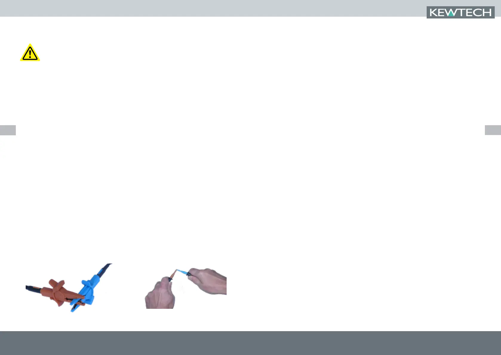
To use the lead nulling feature hold the tips of the test prods very firmly together (or clip the
jaws of the crocodile clips together) and press the ‘CONTINUITY NULL’ button on the tester.
This will start a measurement of the resistance of the pair of test leads and display the result.
Nulling Crocodile clips and prods. Note: The two lower static jaws of the crocodile clips should contact each other when
nulling. Prods should be held very firmly togethe
The word ‘NULL’ will now appear in the display and all subsequent continuity tests conducted by
pressing the Orange test button will automatically deduct this value before displaying the result.
To confirm that this is working press the Orange test button with the prod tips still connected
together and the display should show zero resistance.
You can now use the Orange test button to measure the resistance of a circuit in either manual
or Hands Free mode and the result shown will be that of the circuit tested and not include the
resistance of the test leads.
This will continue as long as the ‘NULL’ indicator appears lit in the LCD, which will be until the
tester is switched off either manually or as a result of the Auto off feature. If the instrument is
powered off by either method it will be necessary to null the leads again before further testing.
Hands Free continuity testing
To enable the hands free feature simply press the HANDS FREE button once, The ‘HANDSFREE’
annunciator will appear flashing on the LCD and will continue to do so until canceled by a further
press of the HANDS FREE button or by changing the function selector switch
When the HANDSFREE annunciator is flashing a single press of the Orange test button will
toggle continuous testing on and off.
Once started a steady beeping tone will be emitted to indicate that measurement is being taken.
After a second or two the test result will be displayed in the primary display area and an audible
tone will indicate either by a single beep that the result is a value under 20 K
Ω or by a short
2-tone alarm that the result is a value over 19.99 K
Ω. The secondary display area will show the
terminal voltage being applied.
The tester will continue to take measurement and any further change to the resistance of the
circuit will be indicated by an audible tone as described above and a change of result on the
display.
A further single press of the test button will suspend measurement.