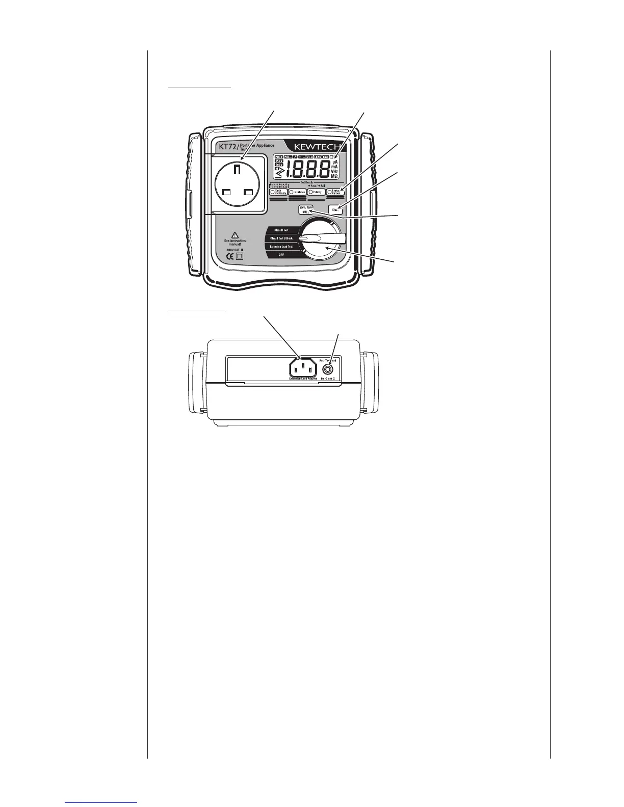
3.4 Instrument layout
Front View
End View
⑴ Test socket
Insert the mains plug of the appliance to be tested in to this socket for
the protective conductor resistance, insulation resistance, substitute
leakage current test and extension lead test.
⑵ LCD
Measured value is displayed
⑶ LED for test result
When the value of protective conductor resistance, insulation
resistance and substitu
te leakage current exceeds the limit dictated by
applicable standards, LEDs light up in red. When it is within the limit,
the LEDs light up in green. (For protective conductor resistance, the
LED can light orange, for details please refer to the note in section 6.1:
Class I Test.)
⑷ Start switch
A measurement starts by pressing this switch.