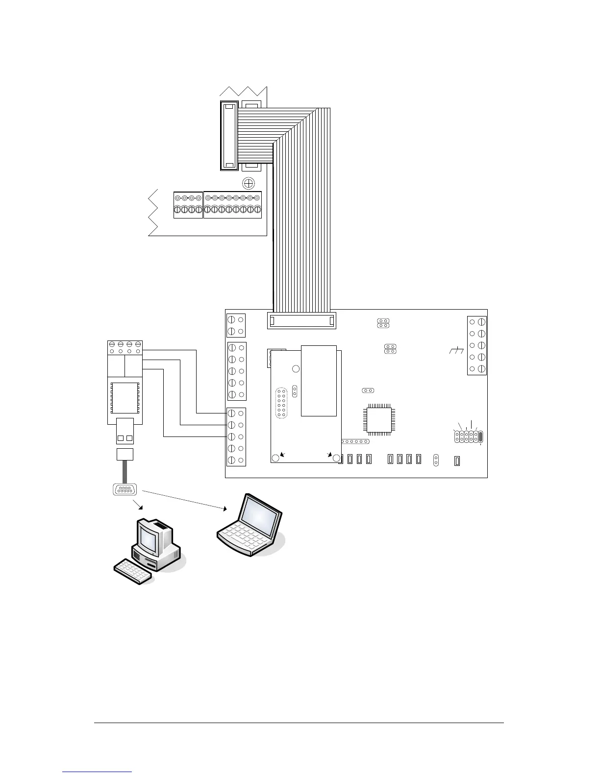
PC or laptop with Keyscan
NETCOM Program Tool Utility.
Use 3 loose
RS-232 wires.
Green
Red
Black
Current Draw : CIM 150 mA +
NETCOMP 140 mA = 290 mA
CIM 0
TD1
RD1
TD2
RD2
GND
RTS1
CTS1
GND
RTS2
CTS2
B3 B2 B1 B0
Diag
J2
RESET
-
CAN2
+
EGND
-
CAN1
+
GND
V +
(+12V)
SCKT1
Tx Data
PC106x
J1
J7
J8
J6
J5
CAN2
CAN1
Rx Data
1 2 1 2 1 2 1 2
COM COM
CAN
CAN
J3
J4
J9
J12
Power
Good
Fault
COM2
HDR1
J10
J11
RJ45
Terminal
Jack
RESET
NETCOMP
Standoffs
To program
NETCOM2P/6P
jumper ON J12
KI-00467E-04-13
COM1
BRN
WHT
GRN
WHT
+ TX - + RX -
485 OUT 485 IN
Connect ribbon cable from
HDR1 on CIM 0 to H2 on
control board. Control board
requires power from DPS-15.
Place a jumper on J12 to set
the CIM for Program mode.
After programming remove
the jumper from J12 to set the
CIM on Run mode. Ensure
CIM 0 has a jumper on J4.
Control Board
(PC 109x)
Common AUX Inputs - E
24
2322
2120191817
H1H2