10) Press to save the changes.
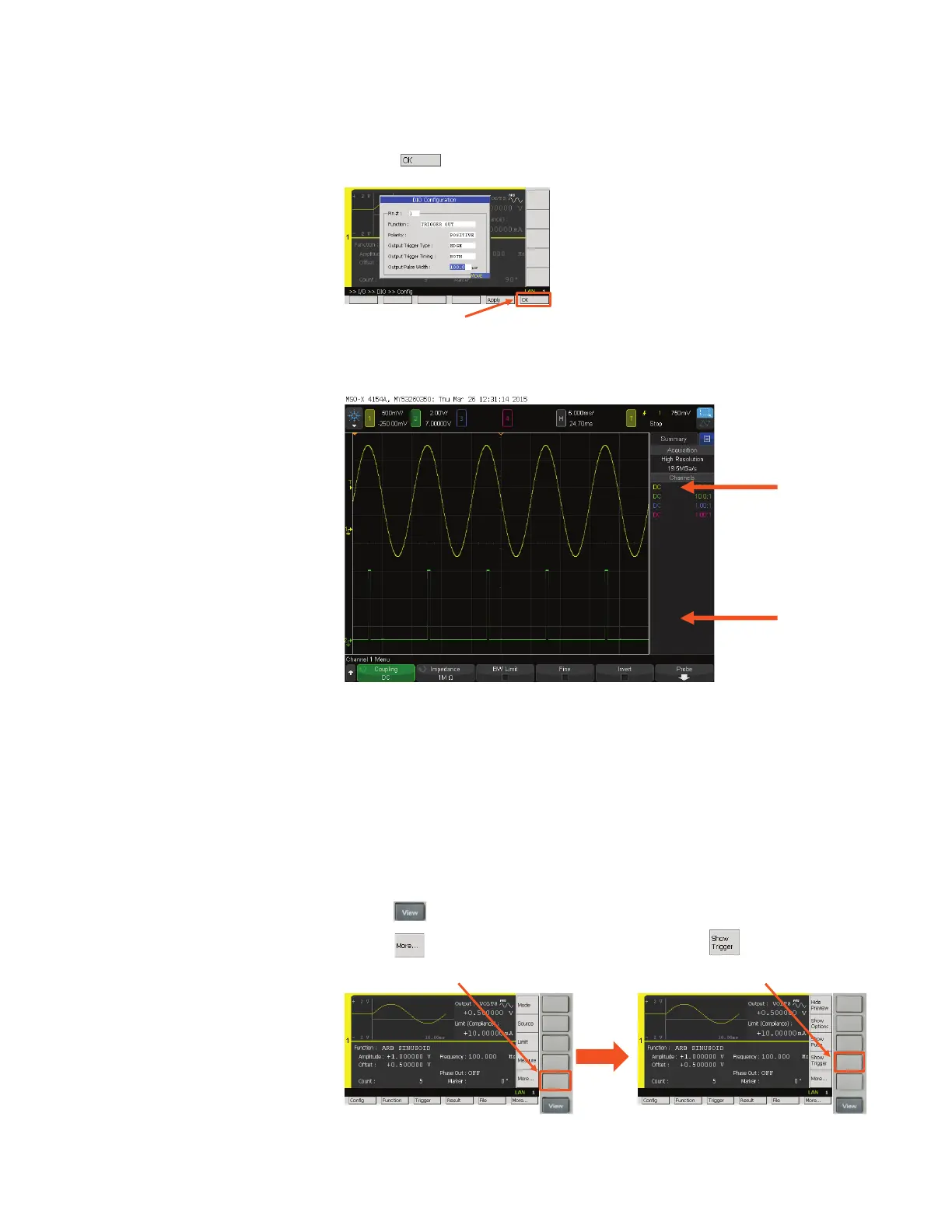
You can now see the monitored output voltage waveform and the phase marker output signal on
the oscilloscope as shown below.
Oscilloscope waveforms
1-3. Monitor the entire output signal on its GUI
The default settings of the B2961A/62A make it monitor only the rst waveform even if multiple
waveforms are congured on the instrument. However, you can modify the Trigger Parameters to
monitor the B2961A/62A‘s entire output and eliminate the need for an oscilloscope.
The following example shows how to modify the B2961A/62A’s parameters to capture the entire
waveform in Graph View.
1) Press repeatedly until the Single View for Channel 1 is shown on the display.
2) Press to toggle the displayed Assist keys, and then press to display the
Trigger Sub-Panel.
Channel
output signal
Phase marker
output from
the Digital I/O
12 | Keysight | Sourcing Precise Current/Voltage Sinusoidal Waveforms Using the B2961A/62A – Demo Guide