Demonstration
To set up the instrument to source a current/voltage sinusoid waveform when the
B2961A/62A receives an external trigger signal, perform the following procedure
to congure the Trigger Parameters.
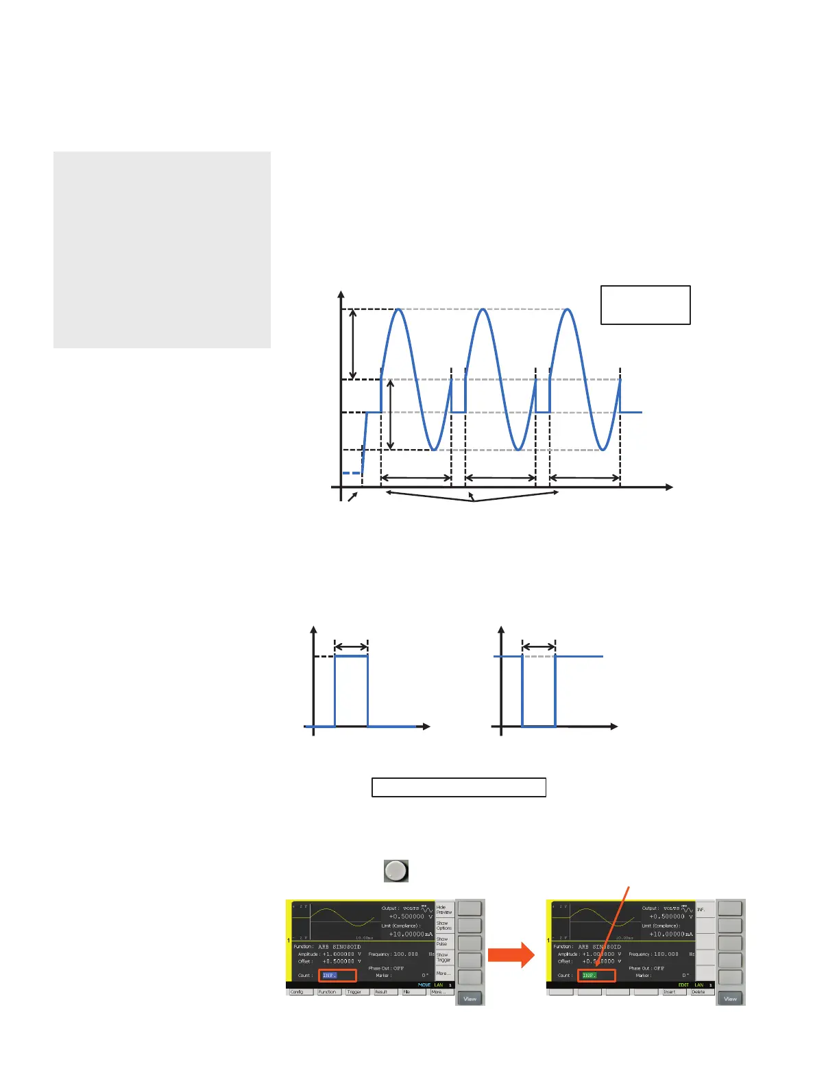
Figure 3 shows the timing diagram for a sinusoid waveform when the instrument
receives an external trigger signal.
Figure 3. Timing chart when sourcing a sinusoid waveform
Figure 4 shows the external trigger signal requirements to initiate device action on the
B2961A/62A. Positive or negative logic can be used.
Figure 4. External trigger signal requirements
1) Rotate and press to edit the Count. Then enter 1 to set the Count to 1.
LAB4: (Optional) Source current/voltage sinusoid waveform when the
B2961A/62A receives an external trigger signal
Objective
Some applications require the
synchronization of the B2961A/62A’s
current/voltage sinusoid waveform
output with other instruments.
This demo shows how to congure
the B2961A/62A to source wave-
forms when it receives an external
trigger signal.
Output ON
Source
Value
Output
Off State
V or I
Time
Offset
V
A
V
A
f
: Amplitude
: Frequency
1/f 1/f 1/f
V
A
External Trigger
t
W
: Trigger Pulse Width > 10 µs
t
W
V
Time
Positive Logic
5 V
t
W
V
Time
Negative Logic
5 V
18 | Keysight | Sourcing Precise Current/Voltage Sinusoidal Waveforms Using the B2961A/62A – Demo Guide