Keysight E4412A and E4413A Operating and Service Guide 13
List of Figures
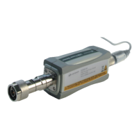
Figure 1-1 E4412A and E4413A power sensors (formerly ECP-E18A
and EXCP-E26A, respectively) . . . . . . . . . . . . . . . .18
Figure 1-2 Relative mode power measurement linearity with power
meter/sensor at 25 ºC (typical) . . . . . . . . . . . . . . . .20
Figure 1-3 E4413A power sensor with adapter . . . . . . . . . . . . . . .26
Figure 1-4 System calibration setup . . . . . . . . . . . . . . . . . . . . . . .27
Figure 1-5 DUT measurement setup . . . . . . . . . . . . . . . . . . . . . . .28
Figure 1-6 Zero set performance verification equipment setup . .31
Figure 1-7 Illustrated parts break down . . . . . . . . . . . . . . . . . . . .34
Figure 1-8 Removing power sensor shell . . . . . . . . . . . . . . . . . . .40