Keysight FieldFox Handheld Analyzers Service Guide 51
Troubleshooting
Measurement Group Troubleshooting
Since the input attenuator is set to 10 dB, there should be 6 dB of conversion
loss from the RF input connector to the I.F. Out connector.
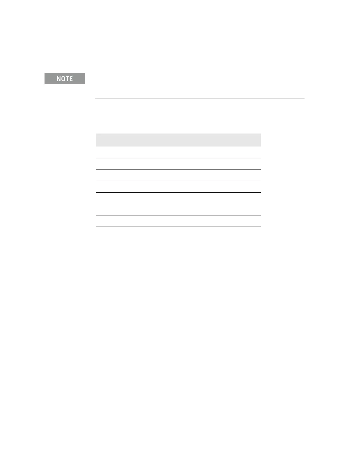
If the input attenuator is changed from 10 dB to 0 dB, the signal will change by
10 dB to -6 dBm. You can verify the input attenuator performance referencing
the table below.
If the 33.75 MHz I.F. Output level is not correct or the input attenuator
performance is out of tolerance, the most likely cause is the A4, R.F. Board.
The 1 GHz test signal was set to 0 dBm. The input attenuator on the analyzer was set to 10 dB. If
the A4 R.F. Board had 0 dB of conversion loss, the 33.75 MHz I.F. output would measure -10
dBm, but it measured -16 dBm because the A4, R.F. Board has 6 dB of conversion loss.
Input Attenuator Setting (dB) 33.75 MHz I.F. Output Level (dBm)
0 6
5 11
10 16
15 21
20 26
25 31
30 36

 Loading...