Testing Performance 3
S-Series Oscilloscopes Service Guide 29
17 Configure the oscilloscope to measure the average voltage on channel 1 as
follows:
a Click Setup > Acquisition.... In the Acquisition dialog box, enable averaging
and set # of Averages to 256.
b Change the vertical scale of the channel under test to 5 mV/div.
c Drag and drop the Average voltage measurement icon onto the channel 1
waveform.
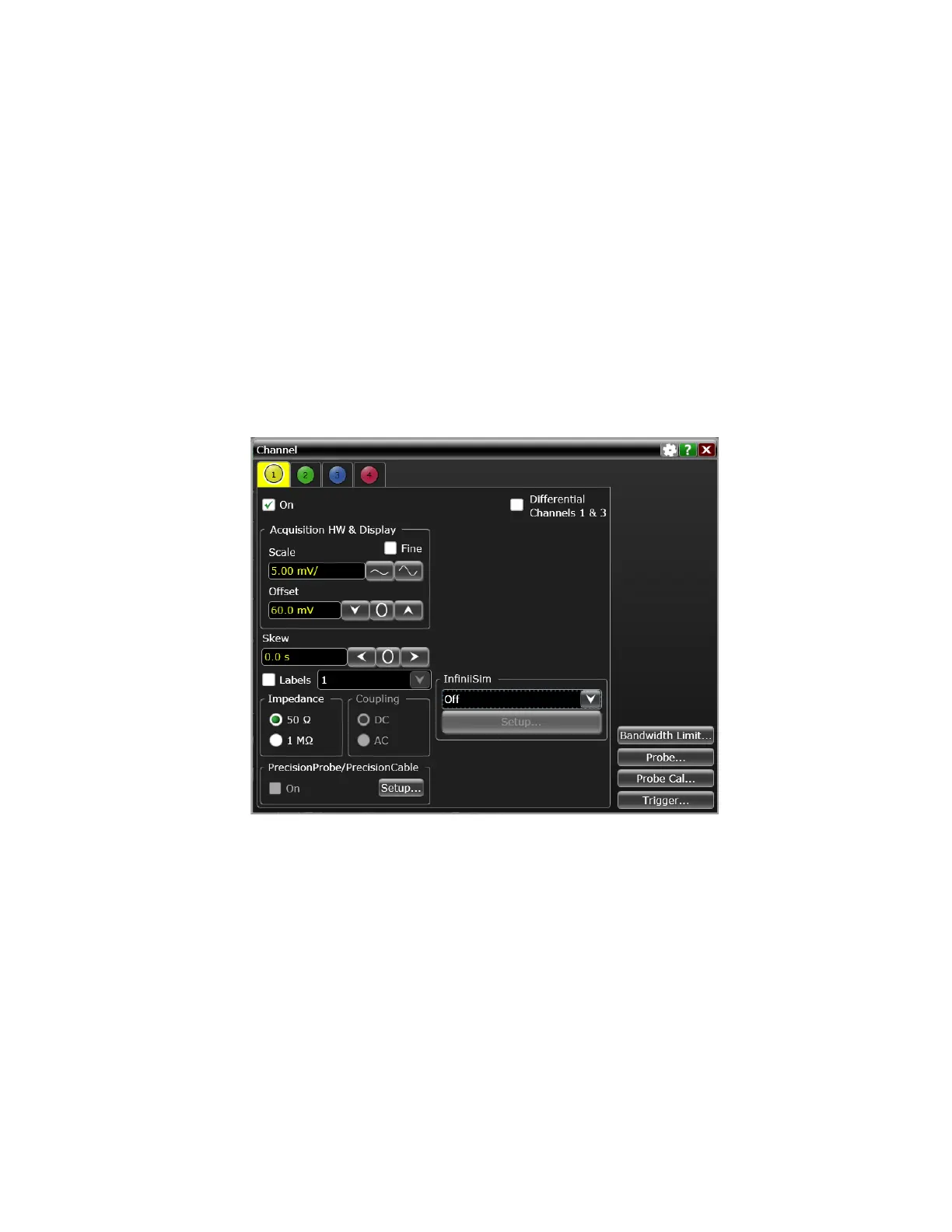
18 Using the Channel dialog box, set the channel’s offset value to 60.0 mV and the
impedance to 50 Ω (or to an offset of 2 V and the impedance to 1 MΩ if this is
your second pass through this test and you are using the 1 MΩ input
impedance version).
19 Set the DC supply voltage (External Supply Setting) to +60.0 mV (or +2 V for
the 1 MΩ version of this test).
20 Press [Clear Display] on the oscilloscope, wait for the number of averages to
return to 256, and then record the DMM voltage reading as V
DMM+
and the
scope V avg reading as V
Scope+
in the Offset Accuracy Test table (either the
50 Ω or the 1 MΩ version depending on which version of the test you are on).
Fill in the V
error+
column by using the following equation:
V
error+
= V
DMM+
- V
scope+
V
error+
must be within the limits specified by the corresponding Offset Accuracy
Limit listed in the table.
21 Change the channel 1 offset value to -60.0 mV (or -2 V for the 1 MΩ version of
this test).
 Loading...


