Do you have a question about the Keysight InfiniiVision 1200 X Series and is the answer not in the manual?
Details regarding the product's warranty terms and conditions.
Terms governing the use of hardware and software.
Specific rights granted to the U.S. government for software and data.
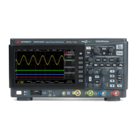
Visual representation of a 4-channel oscilloscope model.
Steps for safely powering on the instrument.
Instructions for connecting probes to the oscilloscope.
Automatically configuring settings for optimal waveform display.
Procedure for calibrating passive probes for accurate measurements.
Overview of the oscilloscope's front panel interface elements.
Understanding the elements and information shown on the display.
Changing the time per division setting for waveform display.
Shifting the trigger point horizontally.
Navigating through acquired waveform data.
Selecting between Normal, XY, and Roll display modes.
Changing the sensitivity (volts/division) of a channel.
Moving the waveform display up or down.
Setting input coupling to AC or DC.
Configuring probe parameters like attenuation and units.
Configuring and displaying analog channel data as a bus.
Tips for optimizing FFT measurements and interpretation.
Understanding and avoiding frequency aliasing in FFT analysis.
Enabling and viewing mathematical operations on waveforms.
Adding, subtracting, or multiplying waveforms.
Performing transform functions like FFT on waveforms.
Storing waveforms in internal reference memory.
Viewing stored reference waveforms for comparison.
Overview of supported serial protocols for decode and trigger.
Configuring trigger settings for serial communication.
Controlling the brightness of displayed waveforms.
Configuring how waveform data is retained on screen.
Adding text notes to the display for documentation.
Controlling the visibility of channel labels.
Applying labels from a library to channels.
Setting the voltage threshold for triggering.
Triggering based on signal edge transitions.
Triggering on pulses of a specific width.
Triggering based on a specific logical pattern of channel states.
Choosing how the oscilloscope handles trigger conditions.
Setting the trigger signal coupling (DC, AC, LF Reject).
Defining the time the oscilloscope waits after a trigger.
Managing the oscilloscope's acquisition states.
Choosing how waveform data is captured (Normal, Peak Detect, etc.).
Capturing infrequent events efficiently by dividing memory.
Placing and adjusting cursors for waveform analysis.
Initiating and configuring automatic waveform measurements.
List and description of available automatic measurements.
Measuring voltage-related parameters like Peak-Peak, Max, Min.
Measuring time-related parameters like Period, Frequency, Width.
Automating mask creation from a reference waveform.
Configuring parameters for mask testing termination.
Viewing and resetting mask test performance statistics.
Steps to activate and configure the DVM feature.
Setting up the oscilloscope and DUT for frequency response analysis.
Configuring and initiating the frequency response analysis.
Choosing and configuring waveform shapes and parameters.
Applying AM, FM, or FSK modulation to signals.
Storing oscilloscope configurations, images, and waveform data.
Loading previously saved configurations and data.
Outputting the screen image to a printer.
Configuring the oscilloscope for network printing.
Configuring remote access interfaces (USB, LAN).
Connecting the oscilloscope to a network.
Configuring display and operational preferences.
Assigning a single key press for repetitive actions.
Connecting to the oscilloscope via a web browser.
Using the web interface for remote operation and programming.
Managing files (setups, images, data) via the web interface.
Technical details and performance parameters of the oscilloscope.
Operating and storage environmental requirements.
Procedures for updating the oscilloscope's software.
Configuring the oscilloscope for CAN bus signal capture.
Setting up triggers for CAN communication protocol.
Configuring the oscilloscope for I2C bus signal capture.
Setting up triggers for I2C communication protocol.
Configuring the oscilloscope for LIN bus signal capture.
Setting up triggers for LIN communication protocol.
Configuring the oscilloscope for SPI bus signal capture.
Setting up triggers for SPI communication protocol.
Configuring the oscilloscope for UART/RS232 signal capture.
Setting up triggers for UART/RS232 communication.
| Sample Rate | 1 GSa/s |
|---|---|
| Channels | 2 or 4 |
| Vertical Resolution | 8 bits |
| Math Functions | Add, Subtract, Multiply, Divide, FFT |
| Time Base Range | 5 ns/div to 50 s/div |
| Interface | USB, LAN |
| Power Supply | 100-240 VAC, 50/60 Hz |
| Memory Depth | 1 Mpts |
| Display | 8-inch WVGA (800 x 480) LCD |
| Input Impedance | 1 MΩ ± 1% |
| Vertical Sensitivity | 2 mV/div to 10 V/div |
| Trigger Modes | Edge, Pulse Width, Video |
| Waveform Update Rate | up to 100, 000 waveforms/sec |
| Connectivity | USB 2.0, LAN |