5-6 Keysight N9912A Service Guide
Theory of Operation
Measurement Group
5-
Measurement Group
The measurement group produces a stable output signal by phase locking a
synthesized voltage-controlled oscillator (VCO).
The measurement group consists of the:
— A4 RF Board
— A5 System Board
— A6 SOM Board
— Main Battery
A simplified RF block diagram is provided in Figure 5-2.
A simplified system block diagram is provided in Figure 5-3.
A4 RF Board
The basic function of the A4 RF board is to provide a signal source and
receivers for the analyzer functions.
There are three sections to the A4 RF board:
—the Common RF section,
— the CAT/NA RF section, and the
— SA RF section.
Common RF Section
This section is common to both NA and SA functions. In this common section,
an LO synthesizer produces a single LO signal from the 30 MHz time base
located on the A5 system board. The LO output is switched between the NA
mixers and the SA first converter depending on the function being used. At any
instant in time, either the NA receivers or the SA receiver may be active, but
not both at the same time.
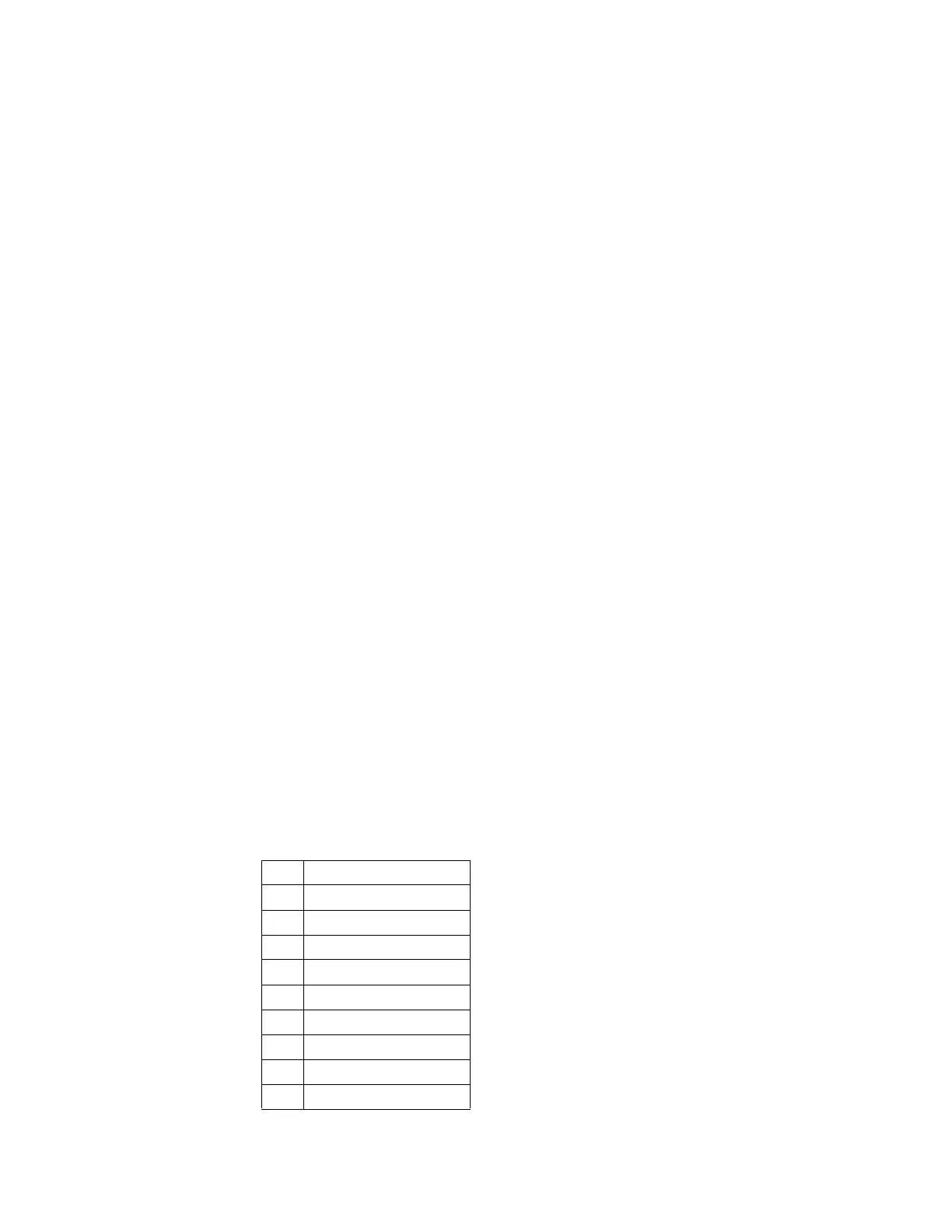
The LO frequency bands are listed below:
1 100 kHz to 1.6 MHz
2 1.6 MHz to 25 MHz
3 25 MHz to 0.2 GHz
4 0.2 GHz to 0.8 GHz
5 0.8 GHz to 1.6 GHz
6 1.6 GHz to 3.2 GHz
7 3.2 GHz to 3.4 GHz
8 3.4 GHz to 4.15 GHz
9 4.15 GHz to 5.1 GHz
10 5.1 GHz to 6.2 GHz

 Loading...


