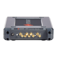
Banded waveguide receiver mini-modules (Virginia Diodes Inc.)
Waveguide ange Frequency GHz Standard receiver only modules High sensitivity receive only module with external
xed attenuator
WR15 47 to 77 N5262BR15 - STD N5262BR15 - 001
WR12 55 to 95 N5262BR12 - STD N5262BR12 - 001
WR10 67 to 110 N5262BR10 - STD N5262BR10 - 001
Notes
1. The high sensitivity modules have the same dynamic range, with about 25 dB lower noise oor and lower saturation point.
2. Modules include a selectable option for use with a 1.2 m cable set (Option 120) or a 5m cable set (Option 500).
3. A power supply is included with each module ordered.
4. All modules are compatible with PNA/PNA-X or test set controller and have cable options for direct connection or test set connections.
Dimensions for waveguide transmission reection modules (Virginia Diodes Inc.)
Module Width Length Height
Standard 5.0 inches 15.275 inches including waveguide, WR1.5 to WR15.
10.25 inches including waveguide WR1.0
3.5 inches (feet adjust +1.25 inches)
Mini-modules 3.0 inches 10.8 inches including waveguide, WR10 to WR15 2.35 inches (feet adjust +0.75 inches)
Waveguide designation equivalent table
MIL-DTL-85/3C IEEE Std 1785.1 Frequency range
WR-15 WM-3759 50 GHz – 75 GHz
WR-12 WM-3099 60 GHz – 90 GHz
WR-10 WM-2540 75 GHz – 110 GHz
WR-08 WM-2032 90 GHz – 140 GHz
WR-06 WM-1651 110 GHz – 170 GHz
WR-05 WM-1295 140 GHz – 220 GHz
WR-04 WM-1092 170 GHz – 260 GHz
WR-03 WM-864 220 GHz – 330 GHz
WR-02 WM-570 330 GHz – 500 GHz
WR-1.5 WM-380 500 GHz – 750 GHz
WR1.0 WM-250 750 GHz – 1.1 THz
Reference: IEEE Standard for Rectangular Metallic Waveguides and Their Interfaces for Frequencies of GHz and Above — Part : Frequency Bands
and Waveguide Dimensions
Banded waveguide transmission reection mini-modules (Virginia Diodes Inc.)
Waveguide ange Frequency GHz Standard transmission
reection modules
Transmission reection modules with 0 to 30 dB mi-
crometer driven attenuator
WR15 47 to 77 N5262BW15 - STD N5262BW15 - 001
WR12 55 to 95 N5262BW12 - STD N5262BW12 - 001
WR10 67 to 110 N5262BW10 - STD N5262BW10 - 001
Notes
1. Modules include a selectable option for use with a 1.2 m cable set (Option 120) or a 5m cable set (Option 500).
2. A power supply is included with each module ordered.
3. All modules are compatible with PNA/PNA-X or test set controller and have cable options for direct connection or test set connections.
Millimeter-wave calibration kits (Virginia Diodes Inc.)
Waveguide ange Frequency GHz Calibration kit
WR2.2 325 to 500 N5262AC02
WR1.5 500 to 750 N5260AC01
WR1.0 750 to 1.1 THz N5262AC01
20 | Keysight | Antenna Test – Selection Guide

 Loading...


