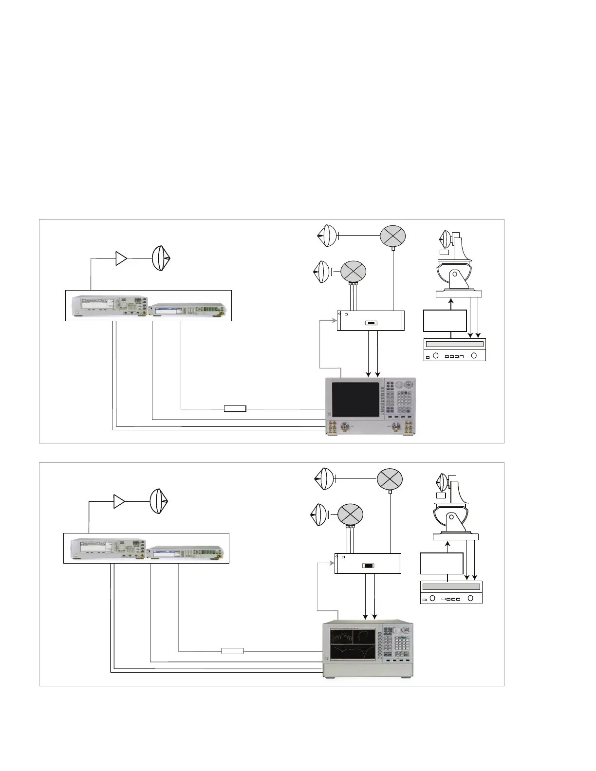
Far-eld antenna measurements
The N5264A PNA-X measurement receiver based system uses 85320A/B broadband
external mixers and a 85309B distributed frequency converter and provides the best
measurement solution (shown in Figure 4). With Option 108, the internal microwave syn-
thesized source can be used as the LO source for the 85309B LO/IF Distribution Unit.
Alternatively, PNA/PNA-X Option 020 or Legacy (E836xC) PNA with Option H11, IF ac-
cess can achieve high sensitivity required for far-eld antenna measurements. Higher
sensitivity can be achieved since the IF signal bypasses the rst down conversion stage
in the PNA/PNA-X, and is routed directly to the input of the second down conversion
stage in the rear panel.
Optional
PSG Synthesized source
Router/Hub
Source antenna
amplifier
Trigger in/out
LAN
LAN
Refer to Table 18
Trigger in/out
85320B
Reference
mixer
85320A
Test mixer
85309B
LO in
PSG or MXG
LO out
10 MHz
10 MHz
AUT
Positioner
Power
Supply
Positioner controller
Note: With Option H11, the rst IF of the PNA
is at 8.33 MHz, so when using H11 inputs, the
user should offset external mixer LO inputs
by 8.33 MHz.
Figure 3. Typical far-eld antenna measurement conguration using a PNA-X network analyzer.
Figure 4. Typical conguration for a compact antenna range using using a PNA-X measurement receiver.
PSG Synthesized source
Router/Hub
Source antenna
Optional
amplifier
Trigger in/out
LAN
LAN
Refer to Table 18
Trigger in/out
85320B
Reference
mixer
85320A
Test mixer
85309B
LO in
PSG or MXG
LO out
(Opt. 108)
10 MHz
10 MHz
AUT
Positioner
Power
Supply
Positioner controller
07 | Keysight | Antenna Test – Selection Guide

 Loading...


