Legacy PNA interface requirements
When conguring the PNA it is critical that power levels are considered to avoid damag-
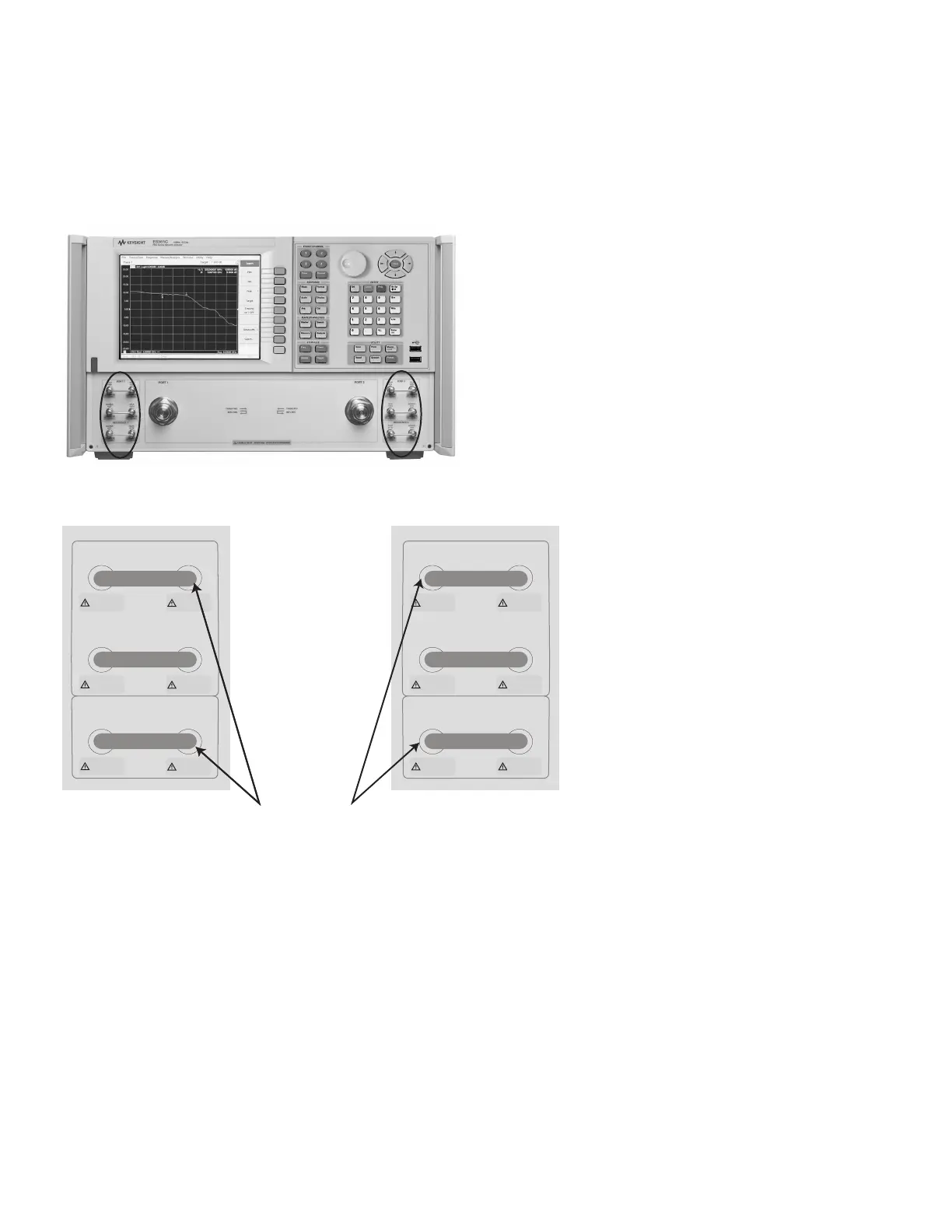
ing the PNA. Ideally, power should not exceed the 0.1 dB compression levels indicated in
the gures below. Damage levels are printed on the instrument, as shown in Figure 20.
Figure 20. PNA E836xC front panel connectors.
+30 dBm +20 dBm
REFERENCE 2
RCVR
R2 IN
SOURCE
OUT
PORT 2
RCVR
B IN
CPLR
ARM
SOURCE
OUT
CPLR
THRU
+15 dBm +30 dBm
+15 dBm +20 dBm
REFERENCE 1
SOURCE
OUT
RCVR
R1 IN
PORT 1
CPLR
ARM
RCVR
A IN
CPLR
THRU
SOURCE
OUT
+15 dBm
+30 dBm
+30 dBm
+20 dBm
+15 dBm
+20 dBm
0.1 dB compression level:
–15 dBm typical at 20 GHz
–25 dBm typical at 50 GHz
36 | Keysight | Antenna Test – Selection Guide

 Loading...


