Option H11 – IF access
Option H11 is only available on the PNA network analyzers. Option H11 also requires
Options 014, 080, 081 and UNL. Option H11 provides direct access to the rst IF down-
conversion stage. The external IF input allows 8.33 MHz IF signals from remote mixers
to be input directly to the PNA digitizer, bypassing the PNA’s RF conversion stage. The
test system becomes a distributed network analyzer with a tracking source and a tuned
receiver. This shifts the dynamic range curves and increases sensitivity by approximately
20 dB.
Option H11 also provides access to the RF and LO signal sources (from 1.7 to
20 GHz) of the PNA on the rear panel. This dual hybrid source eliminates the need for a
separate stand alone synthesizer when remote mixing is used. There is no power control
over the rear panel RF and LO signals. Power output ranges vary and external ampli-
ers may be needed to achieve the power level required by the mixers. Table 2 shows the
typical power levels available at the outputs. By removing the necessity of an external
RF source the test time is dramatically reduced. This is because the frequency stepping
speed is solely a function of the PNA where the settling time is in the uS range as com-
pared to mS range of most sources.
Table 2. Typical values of the RF and LO outputs from the rear panel of the PNA
Rear Panel LO Power (Typical)
1.7 GHz to 20 GHz –16 to –7 dBm
Rear Panel RF Power for E8362C (Typical)
1.7 GHz to 20 GHz –16 to –5 dBm (at –5 dBm test port power
1
)
Rear Panel RF Power for E8363C/E8364C (Typical)
1.7 GHz to 10 GHz –12 to –2 dBm (at –5 dBm test port power
1
)
10 GHz to 16 GHz –8 to 0 dBm (at –5 dBm test port power1)
16 GHz to 20 GHz –1 to +5 dBm (at –5 dBm test port power
1
)
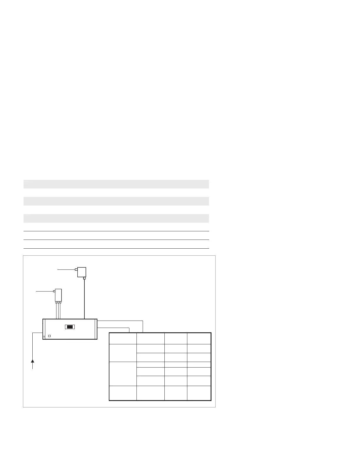
Figure 24. PNA E836xC network analyzer Option H11 and Option 014 connection diagram and input level
requirements.
85309B
Test IF
Ref IF
LO input
85320B
Reference mixer
85320A
Test mixer
Pin ~7.5 to 16
dBm
Pout = 19 dBm Pout = 19 dBm
LO in
RF in
RF in
Pin < 26 dBm
Pin < 26 dBm
RF out from PNA
Input Freq
Max input
(.1 dB)
Front Option 014
A, B, R1, R2
20 MHz –10 dBm
Rear Option H11
A, B, R1, R2
8.33 MHz –27 dBm
Test port
PNA-X N5242A
network
analyzer
Direct access
receiver
PNA-X N4264A
measurement
receiver
IF inputs
20 MHz
20 MHz
Refer to
Table 18
+8 dBm
–6dBm
–9 dBm
Rear inputs
Option 020
Refer to
Table 18
–9 dBm
PNA E836xC
network
analyzer
Pin ~7.5 to 16 dBm
1. Test port power has to be at a high
enough level such that the Drop Cal does
not occur. If Drop Cal occurs, then the
power out of the rear panel RF connector
will drop by about 15 dB.
39 | Keysight | Antenna Test – Selection Guide

 Loading...


