Test set
LO
RF
Pulse in
R2
B
0.1 dB Compression point:
–27 dBm
Damage level: –20 dBm
Minimum IF gate width: 20 ns for less than 1 dB deviation from
theoretical performance (internal gates)
DC damage level to pulse connector inputs: 5.5 Volts
Drive voltage: TTL (0,+5.0) Volts
Gate input impedance: 1Kohm
R1 A
8.33 Mhz IF in
R2
B
R1 A
Triggering (remote access):
- BNC connectors
- Edge-triggering (pos/neg)
- Trigger in/out
- Remote access with SCPI
- Available on PNA models E8361C,
E836xC, and N5230C.
Option H11 Connectors:
- PNA RF source and LO outputs for
external mixing
- Pulsed measurement capability with
Option 008
- Direct access to the internal IF
LO output
N5264A Option
108:
+10 dBm typical
N5242A:
0 to +6 dBm
IF inputs
0.1 dB Compres-
sion point: –9 dBm
Damage level:
+23 dBm
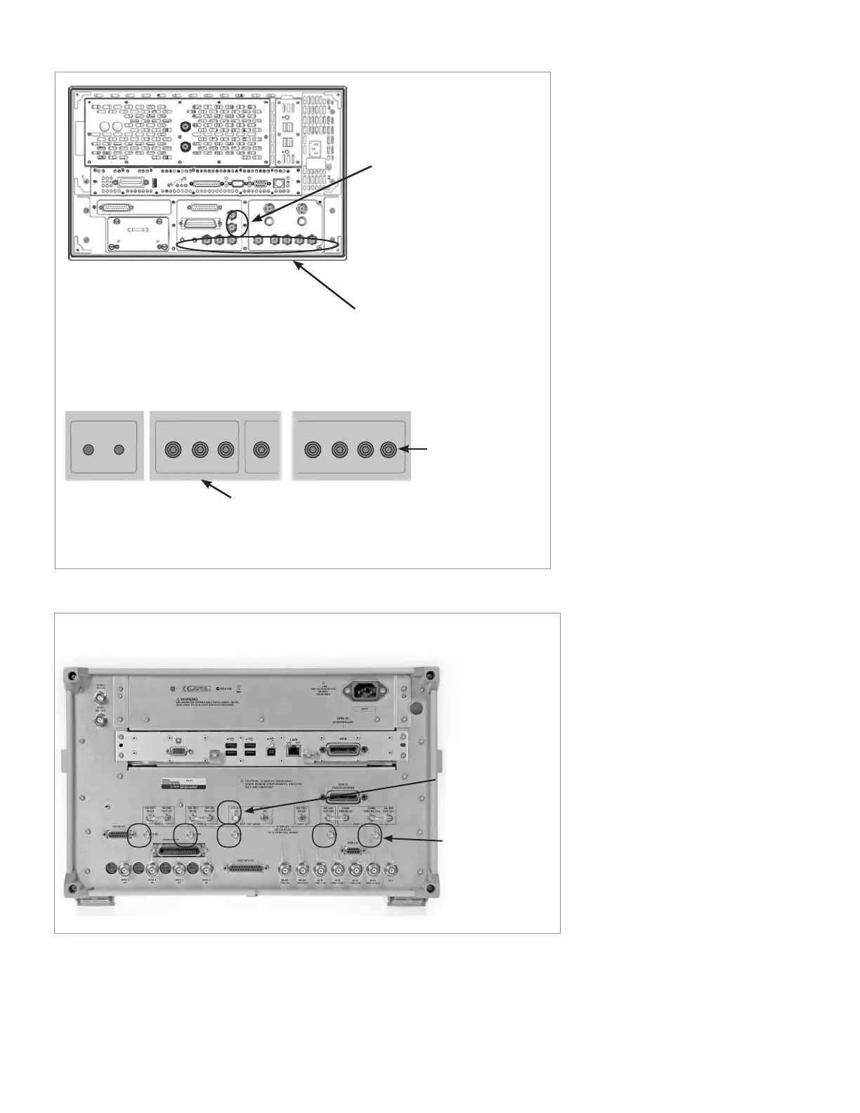
Figure 22. PNA E836xC network analyzer rear connectors.
Figure 23. PNA-X N5242A network analyzer and PNA-X N5264A measurement receiver
rear connectors.
38 | Keysight | Antenna Test – Selection Guide

 Loading...


