Drive levels
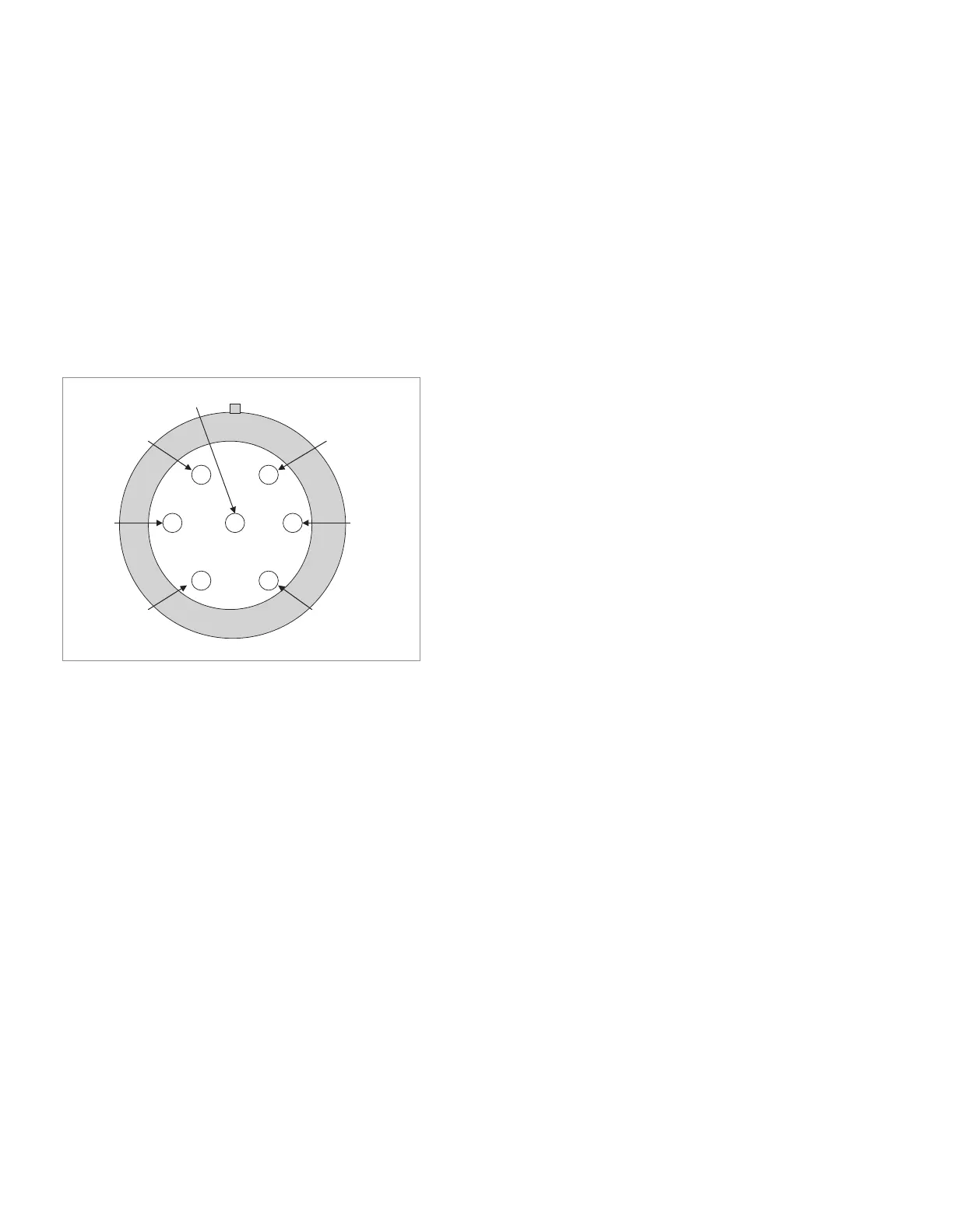
Refer to Figure 56 for pin locations. Note the notch and red mark on the bias connector
outer ring are used for reference.
To turn ON a port, supply a –7VDC (± 0.35V) bias voltage.
Current is approximately 41 mA.
To turn OFF a port, supply a +6.3VDC (± 0.32V) bias voltage.
Current is approximately 95 mA.
Only one port can be turned on at a time, or all ports can be off.
The total current is approximately 400 mA for 85332B, 200 mA for 85331B with all
ports off.
Figure 56. Bias connector pin locations (enlarged).
Pin 1 = Port 1 on/off bias
Pin 2 = Port 2 on/off bias
Pin 3 = Port 3 on/off bias (not connected for 85331B)
Pin 4 = Port 4 on/off bias (not connected for 85331B)
Pin 5 = Common/ground (0VDC)
Pins 6,7 = Not Connected
Size and weight
65 mm (2.6 in) x 70 mm (2.75 in) x 70 mm (2.75 in)
Approximately 0.35 kg (0.7 lbs)
Environmental
Operating conditions
Temperature –20 to 55 °C (–4 to 131 °F)
Humidity 5 to 95% at 40 °C or less (non-condensing)
Non-operating conditions
Temperature –40 to 70 °C (–40 to 158 °F)
Humidity 5 to 95% at 65 °C or less (non-condensing)
Power
Supplied by external controller
Pin 6
Pin 5
Pin 4Pin 3
Pin 7
Pin 1
Pin 2
Note: Keysight channel partners can provide
the control, interface and timing required for
these PIN switches.
71 | Keysight | Antenna Test – Selection Guide

 Loading...


