Assemble units as described herein only. To do otherwise
may result in instability. All screws, nuts and bolts must be
tightened securely and must be checked periodically after
assembly. Failure to assemble properly, or to secure parts
may result in assembly failure and personal injury.
3
WorkUp Adjustable Table - Model CR
Assembly Instructions
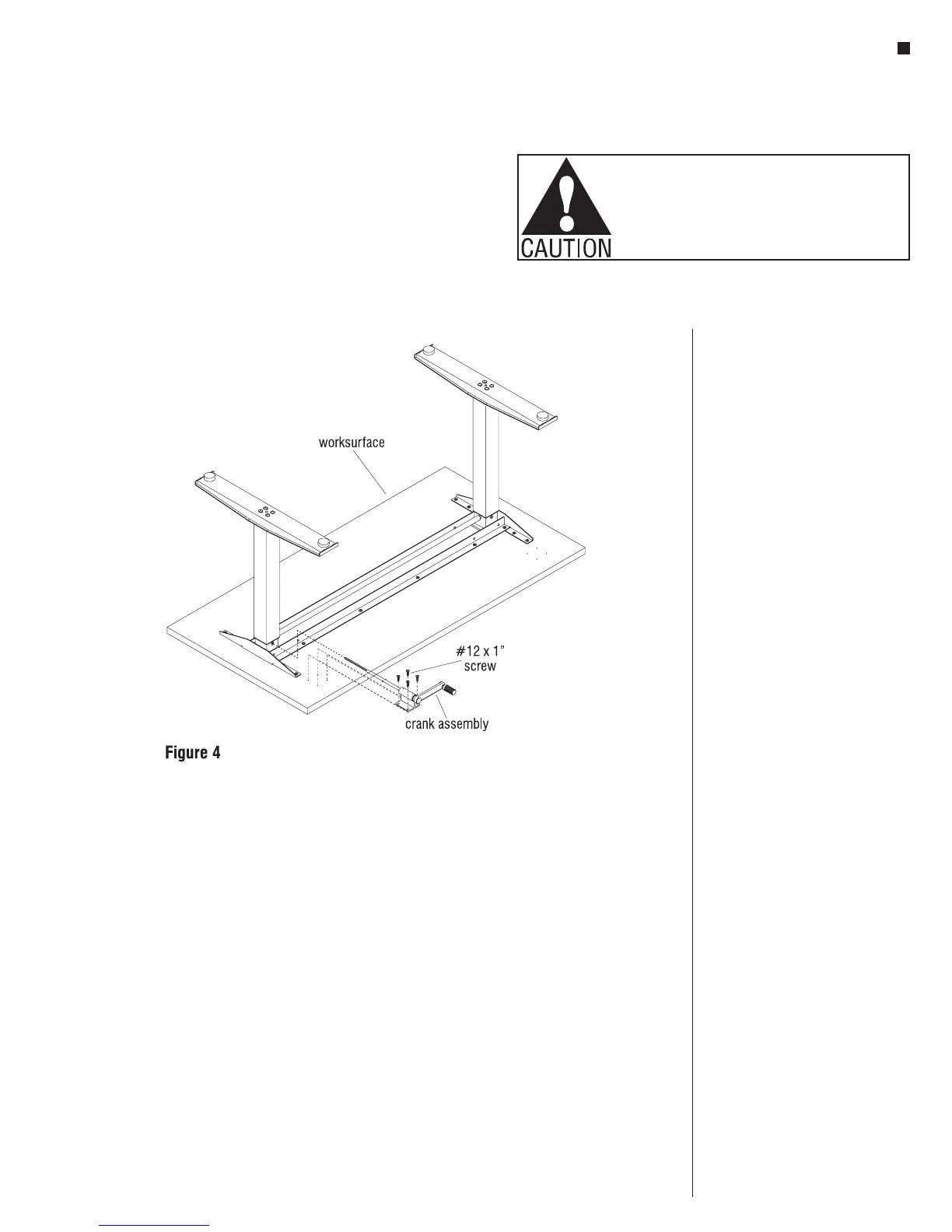
Assemble Crank
Note: The crank can be installed on
either (left or right) side of table.
1. Slide the hex rod of the
Crank Assembly into the hex
bushing on one of the columns
(Figure 4).
2. Attach the Crank assembly using
four #12 x 1” tapping screws
(Figure 4).
Note: If the crank handle binds when
moved in and out, slightly loosen the
four attachment screws, reposition the
mount housing until the handle does
not bind, and re-tighten the screws.
3. Carefully invert the table to its
upright position. Caution: The
table is very heavy. Two or more
people are required to turn the
table upright.
4. Adjust leveling glides to level the
table.
Operating the Table
Note: When adjusting the table always
be sure hands are clear of any potential
pinch areas created by the table and
adjacent furniture.
1. The table can be adjusted to
the desired height by gently
pulling the crank handle out of
the stored position and cranking
clockwise to raise the table and
counterclockwise to lower the
table. Once the table is at the
desired height the handle can be
pushed in to the stored position.
Product Information
Maximum Load: The allowable load
is based on the size of the worksurface
and shall be evenly distributed on the
worksurface.
Allowable Load = Perimeter x 1.5 lbs.
Example: the allowable load
for a 30x66 worksurface is
192 x 1.5 lbs. = 288 lbs.