5
Assemble units as described herein only. To do otherwise
may result in instability. All screws, nuts and bolts must be
tightened securely and must be checked periodically after
assembly. Failure to assemble properly, or to secure parts
may result in assembly failure and personal injury.
Seminar
TM
Tables with 4-Wire Power System - Bases & Tops
Assembly Instructions
Seminar Table Base & Top
Installation (cont.)
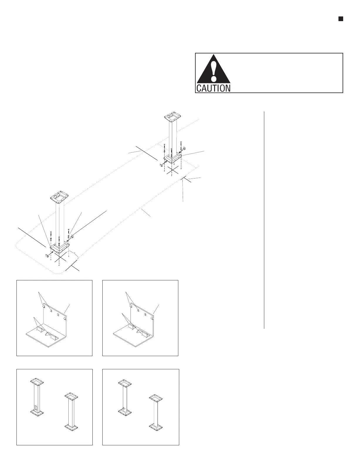
3. Refer to the space-planning layout
and Figure 2 above, to accurately
mark for base flange mounting
locations on the floor (Figure 2).
Note: On carpeted floors, it is
recommended that the carpet be
removed directly under the base
flange for full contact of the base with
the floor. If carpet is not removed, the
floor anchors must be retightened
after two weeks of use.
4. Identify the different base types to be
used on the installation (Detail A or
B). Lay out the bases according to
the locations specified on the
space-planning layout. Position the
base on the floor at the center mark
where the base will be installed.
Determine if bases are to be
installed: (a) over the carpeting or (b)
with carpeting removed.
(a) With the base correctly centered
over the marks on the floor, mark
where the anchor holes are to be
drilled into the floor. Using a
1
/
2
”
diameter hollow punch, cut out
carpeting for anchor holes. Read note
below and go to step 5.
Note: After two weeks of use, the
base flange mounting fasteners must
be rechecked for tightness.
(b) With the base correctly centered
over the marks on the floor, mark
around the perimeter of the base
for removal of the carpeting. Cut
and remove the carpeting. Mark the
anchor hole locations on the floor.
Note: If power infeed is to be run
from below the floor (no exposed
connections), the wires should be
run up through the column prior to
installing the base flange to the floor.
5. Bore anchor holes to minimum
1
/
4
” x 2
3
/
4
” hole depth for concrete
anchors, or
9
/
32
” hole for wood floor,
with flat washer and lock washer
(not included). Locate base over
pre-drilled holes and drive in (do not
tighten) mounting fasteners. Shim
under base ange with steel
washer(s) as needed to level or
compensate for oor variances.
See shim instructions
(KI-62058) included with shim
kit (Figure 2).
6. For Basic (rectangular) and Select
(oval) bases, use the silver flange
clips (12.0951). Center flange clips
under both 6” sides of base flanges,
with the barbs up. Insert the locating
tabs of the flange so that they are
tight into the base flange notches for
proper engagement of flange covers
later. After all bases are positioned
and adjusted with shims, securely
tighten base flanges to the floor
(Figure 2). Do not install plastic
flange covers until step 11.
see space-planning layout
Figure 2
lag bolt
with locking
&at washer
base
ange
front edge
of tabletop
front edge mark
front-to-back center line
front-to-back center line
base
ange
silver ange clip
(12.0 )951
Black BasicFlange Clip - Base
Silver Basic&SeleFlange Clip -ct
silver ange clip
( base)basic & select
(12.0 )951
black ange clip
(for base)basic
(12.0 )950
barbs
locating
tabs
barbs
locating
tabs
Detail BDetail A
Select Base Identication
Basic Base Identication
Seminar Basic Base
(rear electrical infeed)
Seminar Basic Base
(no electrical infeed)
Seminar BaseSelect
(rear electrical infeed)
Seminar ct BaseSele
(no electrical infeed)
 Loading...