4
Assemble units as described herein only. To do otherwise
may result in instability. All screws, nuts and bolts must be
tightened securely and must be checked periodically after
assembly. Failure to assemble properly, or to secure parts
may result in assembly failure and personal injury.
Seminar
TM
Tables with 4-Wire Power System - Bases & Tops
Assembly Instructions
Seminar Table Base & Top
Installation
Note: When installing
Seminar Tables equipped with the
power module or undersurface
power, extra care must be taken to
hold very close tolerances to the
dimensions shown on the
space-planning layouts. Failure to
follow the dimensions shown may
prevent proper installation of the
electrical components.
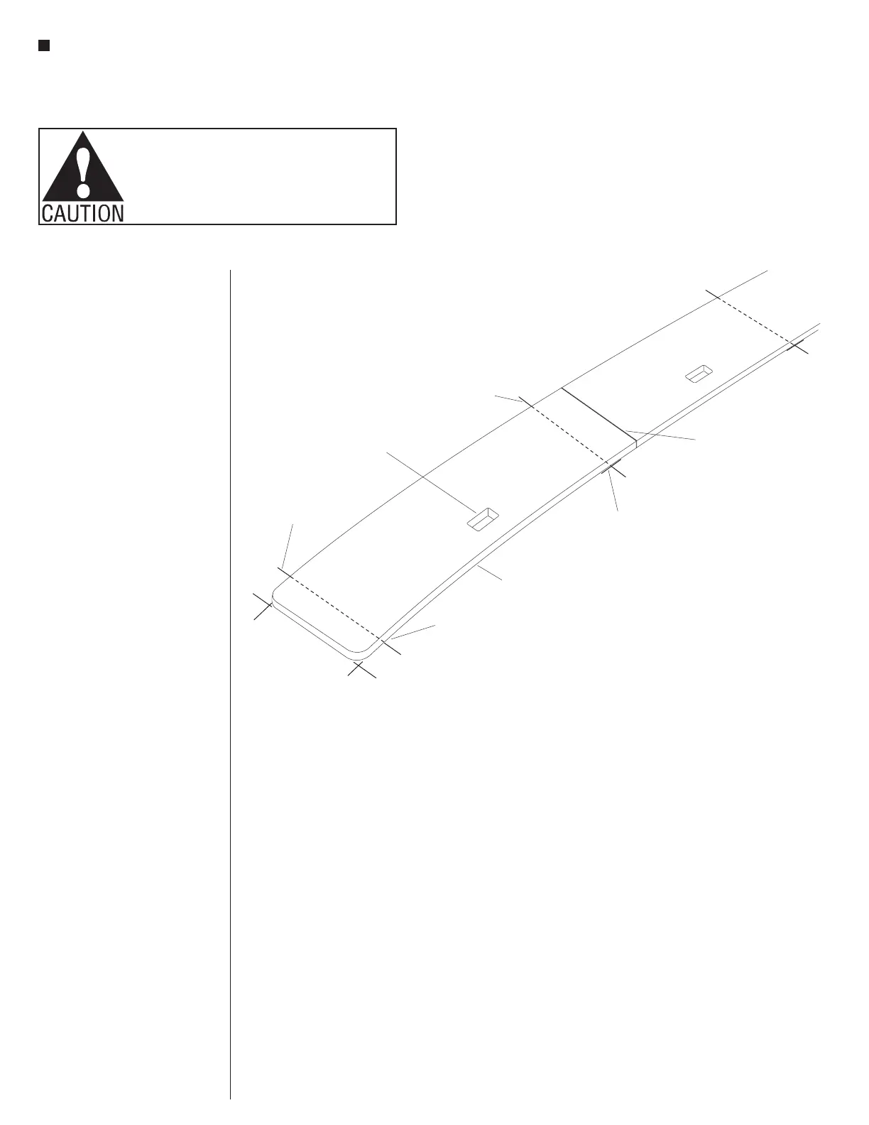
1. Refer to the space-planning layouts
and the identification numbers on the
underside of the tabletops. Carefully
position tops on the floor, top side
up, at the location that they will be
installed later (Figure 1).
2. With the tops properly laid out on
the floor, refer to the space-planning
layouts to determine the front-to-back
center line locations for base flanges.
Mark the front-to-back center line
location for each base flange on the
floor at the front and rear edge of the
tabletops. Make a perpendicular mark
at the front edge of the tabletops
(Figure 1). Move the tabletops back
far enough to make the final marks
for the position of base flanges.
front-to-back center line
front edge mark
front edge mark
front edge of table top
front-to-back center line
table joint
Figure 1
module hole
(with PowerUp only)
tabletop