3
Assemble units as described herein only. To do otherwise
may result in instability. All screws, nuts and bolts must be
tightened securely and must be checked periodically after
assembly. Failure to assemble properly, or to secure parts
may result in assembly failure and personal injury.
Seminar
TM
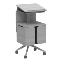
Tables with 4-Wire Power System
Assembly Instructions
TOOLS REQUIRED
• Quick clamps
• Level
• Hammer drill and bit for concrete
anchor holes
• Drill and bit for pilot holes in
wood floor
• Socket set
• #2 and #3 Phillips head
screwdriver bits
• Tape measure
• C-clamps
• Caulk gun
Note: Read these assembly
instructions carefully prior to product
installation. Product failure may
result if instructions are not followed.
MINIMUM CONSTRUCTION
REQUIRED FOR FLOOR
MOUNTING
Wood Floors
• Minimum two sheets
3
/
4
” thick
plywood
• APA rated grade plywood
• Allow minimum embedment 1
1
/
2
”
with lag screws
Concrete Floors
• 3000 psi Concrete compressive
strength
• 3” thick free of obstructions for
1
1
/
2
”
• Riser to be plumb within
1
/
8
degree
• Minimum anchor embedment
1
1
/
2
”
Note: Warranty null and void if
KI product is installed on flooring
not meeting minimum structural
requirements stated above.
FLOOR FASTENER
REQUIREMENTS
Wood Floors
•
5
/
16
” x 2
1
/
2
” hex washer head
tapping screw
• Four bolt assemblies required per
upright
Concrete Floors
•
1
/
4
” Hilti KH-EZ x 2
5
/
8
”
• Max torque: 18 ft/lbs
• Four screw assemblies required
per base
Note: Floor mounting fasteners are
not provided, unless specified.
• For questions concerning anchor
selection and special floor
conditions, please contact KI
Customer Service at
1-800-424-2432.
STEPS FOR INSTALLATION
1. Read and review Assembly
Instructions.
2. Review space-planning layout.
3. Review job site and verify field
conditions.
4. Verify floor structural conditions.
5. Stage product for installation.
6. Locate and mark reference points
to floor.
7. Locate and install columns and
tabletops. If any below floor power
infeed runs up any column, install
infeed in column before installing
column to floor.
8. Attach duplex receptacles to
underside of table.
9. Install power infeed and receptacle
Jumpers.
10. Install receptacle hub shrouds and
jumper covers.
11. Connect power infeed to building
power source (electrician) (for
4-Wire Power System).
12. Check mechanical and electrical
operation (for 4-Wire Power
System).
13. Install modesty panel and other
accessories if required.
14. Clean product and site.
15. Walk through with installation crew
to assure the product has been
installed per assembly instructions
and space-planning layout.
16. Perform final walk through with the
customer. Receive sign off.
Note: Dimensional spacing
referenced is center line to center
line unless otherwise noted.
 Loading...