8
Hub
®
Seating - Ganger Kit
Assembly Instructions
Assemble units as described herein only. To do otherwise
may result in instability. All screws, nuts and bolts must be
tightened securely and must be checked periodically after
assembly. Failure to assemble properly, or to secure parts
may result in assembly failure and personal injury.
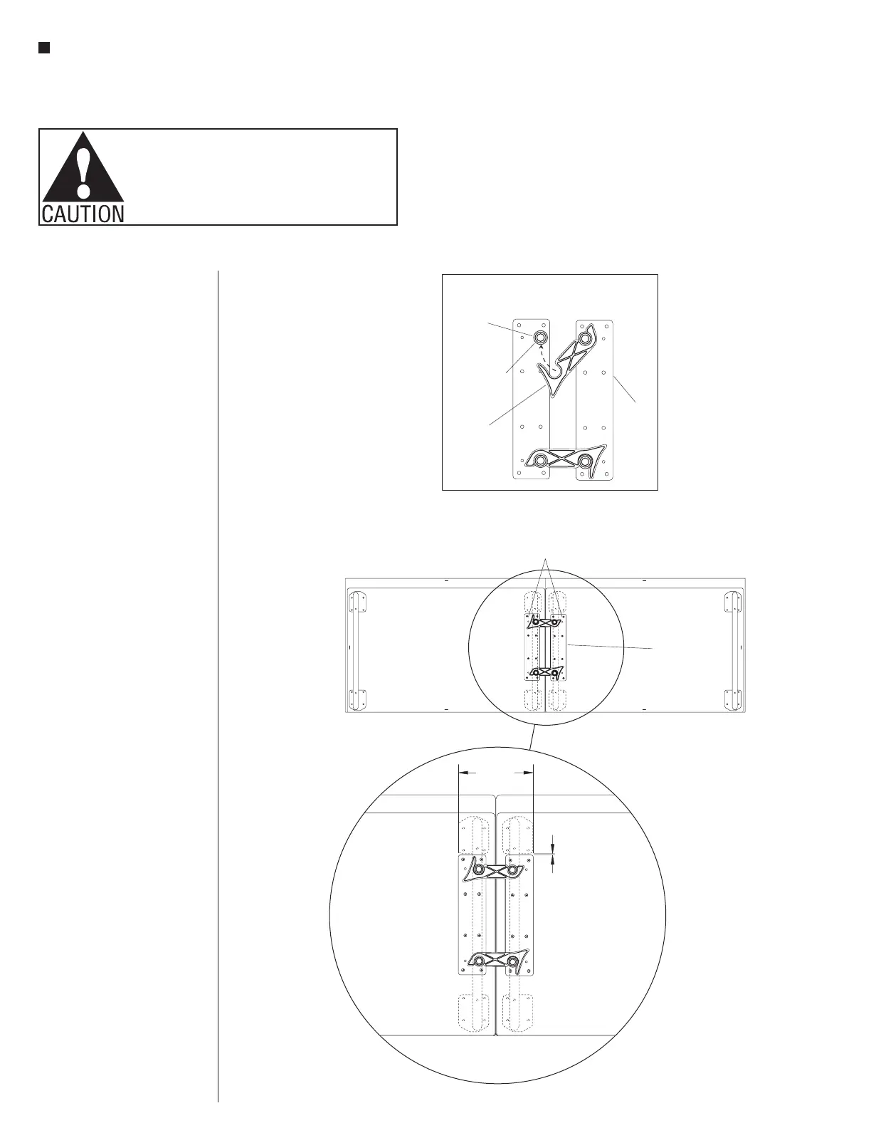
Hub Ganging Assembly (cont.)
4. Locate a pair of ganging plate
assemblies and orient them as
illustrated on a flat, firm surface.
Latch the hooks to the opposing
pegs, snapping together firmly as
illustrated (Detail B).
5. To install ganger mounting
plates, one person must first
apply pressure, holding two
modular seating units tightly
together while also holding
seat bottoms flush. Then,
another person is to position
the joined ganger pair to the
underside of the two units. The
ganger mounting plates must
be positioned
1
/
8
” away from the
front base mount bracket, and
also be centered evenly between
the units as illustrated (Figures 2
& Detail C).
Figure 2 - Bottom View
Note: center
gangers evenly
between modular
seat units
Detail C - Side-to-Side Ganging
FRONT OF UNIT
1
/”
8
Side-to-Side Ganging Assembly - cont.
5. To install ganger mounting plates, one person
must first apply pressure, holding two modular
seating units tightly together while also holding seat
bottoms flush. Then, another person is to position
the joined ganger pair to the underside of the two
units. The ganger mounting plates must be
positioned up, to be 1/8” from touching the front
base mount bracket and also be centered evenly
between the units as illustrated (Figures 1 & 2, Detail
C).
side-to-side and back-to-back gangers are
mounted with different specifications.
Note:
Reference
page 4 for back-to-back ganging.
6. Use the mounting holes of the correctly positioned
ganger plate as a "drill template" and pre-drill
mounting holes into the bottom of the units using a
5/32" drill bit and power drill. While holding the units
tightly together, secure the hooked-together ganger
mounting plates to the bottoms of the units using a
drill driver, #2 bit and all sixteen #10 x 1 Phillips
screws provided (Figures 1 & 2, Detail C).
7. If more than three units are to be ganged side-to-
side for the final configuration, the unit(s) to receive
additional ganging must be un-hooked from the unit
next to it. Repeat the previous steps for additional
modular units to be connected side-to-side. Un-
hooked units can be re-ganged after all in the
configuration have been carefully tipped to the
upright position and placed to their final location.
Important: “Final
Alignment & Installation”
Read page 6 instructions
before tipping any ganged
seating units to the upright position.
ganging plate
assembly pair
centered
Detail B
orient pegs
and hooks as
illustrated below
latch hook to
the opposing
peg firmly
hook
peg
ganging
plate
assembly
 Loading...