1-206-235975-001 November 2002
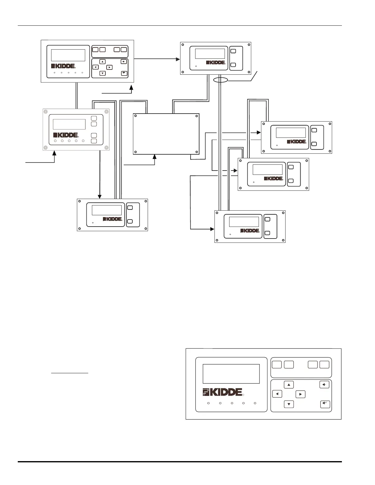
Kidde Gemini II System
RHU#1
w/ Display
RDU # 1 for MCP
RDU # 2 for RHU # 1
Main Control Panel
RHU#2
w/o Display
Class A, Style 7
RS-485 Data Pairs.
Max. length 4,000 ft. each.
120/240
Vac
24 Vdc
24 Vdc
24 Vdc
RDU # 4 for RHU # 2
RDU # 3 for RHU # 2
RHU#2
RDU # 5 for
120/240
Vac
120/240
Vac
Note:
The system must comprise 1 MCP.
To expand, add up to 7 RHUs and
up to 16 RDUs to the network.
POWER
REMOTE DISPLAY UNIT
R
R
ALARM
SCROLL
SUP/TBL
SCROLL
SYSTEM
CONTROLS
POWER
REMOTE DISPLAY UNIT
R
R
ALARM
SCROLL
SUP/TBL
SCROLL
SYSTEM
CONTROLS
POWER
REMOTE DISPLAY UNIT
R
R
ALARM
SCROLL
SUP/TBL
SCROLL
SYSTEM
CONTROLS
POWER
REMOTE DISPLAY UNIT
R
R
ALARM
SCROLL
SUP/TBL
SCROLL
SYSTEM
CONTROLS
POWER
REMOTE DISPLAY UNIT
R
R
ALARM
SCROLL
SUP/TBL
SCROLL
SYSTEM
CONTROLS
MAIN
CONTROL
PANEL
POWER ON
ALARM
TROUBLE
SUPERVISORY
SIGNAL
SILENCED
RESET
ALARM
SCROLL
SYSTEM
CONTROLS
SIGNAL
SILENCE
SUP/TBL
SCROLL
MENU
CONTROLS
CANCEL
ACCEPT
R
R
SIGNAL
SUPERVISORYPOWER ON
ALARM
UNIT
TROUBLE
SIGNAL
SUP/TBL
SCROLL
REMOTE
HAZARD
ALARM
SCROLL
CONTROLS
SYSTEM
RESET
SILENCE
SILENCED
R
R
sors. Based on pre-programmed instructions, and your own
configuration parameters, outputs are generated to release
agent or activate a sprinkler system, shutdown equipment
and annunciate an alarm.
All alarms, troubles and supervisory signals received at the
panel are logged and displayed for the operator. While not
every alarm results in an agent release, those that do are
called decisive alarms. The conditions under which a deci-
sive alarm occursand what happens afterwardsare de-
scribed in Paragraph 3-2, Agent Releasing Logic.
1-4.1 Display Panel
The front of the Main Control Panel contains five LEDs and
a 4 line x 20 character display window for text messages.
See Paragraph 2-2 for information on operating the display
panel.
A buzzer provides an audible warning of a system alarm or
trouble. It sounds continuously when a new alarm or trouble
is detected and can be silenced with the SILENCE button.
Scroll buttons are provided to view current alarm, supervi-
sory and trouble messages.
The RESET button removes power from the initiating cir-
cuits, thereby resetting the detectors.
Arrow keys provide access to the menu system where con-
figuration parameters for the Main Control Panel and all
other remote units may be entered and reviewed.
MAIN
CONTROL
PANEL
POWER ON
ALARM
TROUBLE
SUPERVISORY
SIGNAL
SILENCED
RESET
ALARM
SCROLL
SYSTEM
CONTROLS
SIGNAL
SILENCE
SUP/TBL
SCROLL
MENU
CONTROLS
CANCEL
ACCEPT
R
R
09-17-02
ALM00 SUP0 TBL00
MCP v1.BA
SYSTEM STATUS NORMAL
12:00
Figure 1-2. Main Control Panel, Front Display Panel
Figure 1-1. Typical UL System Diagram