Chapter 1: Introduction
VM-1 User Guide 3
• One Ethernet connection for panel programming and diagnostics
• Live voice and prerecorded audio messaging
• Two-way firefighter telephone communication
• Connection to a VM-1 life safety network using copper, fiber optics, or both
(maximum network size may not exceed 24 nodes)
Overview of panel controls and indicators
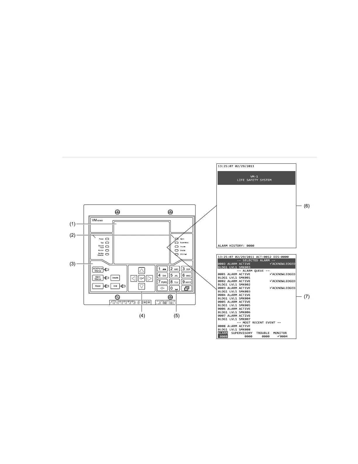
Figure 1: VM-LCD User Interface
(1) Display
(2) System status indicators (see Figure 4 on page 5 for details)
(3) Common Controls keypad (see Figure 5 on page 6 for details)
(4) Cursor keypad (see Figure 6 on page 7 for details)
(5) Alphanumeric keypad (see Figure 7 on page 7 for details)
(6) Normal display screen (see Figure 2 on page 4 for details)
(7) Off-normal display screen (see Figure 3 on page 4 for details)