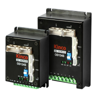
The Kinco OD series servo driver is an ultra-small volume device designed for applications with limited installation space. Its modular design allows for quick integration into control schemes and customized development for various user conditions.
Function Description:
The OD series servo driver is designed to control low-voltage servo motors ranging from 50W to 750W. It supports various encoder types, including photoelectric, magnetic, and incremental encoders, enabling precise motor feedback. The driver features dual power supply support, enhancing system stability and simplifying on-site debugging. It also supports multiple communication protocols such as CANopen, EtherCAT, RS232, and RS485, allowing seamless integration with mainstream controllers like Omron and Beckoff. Additionally, the device offers specific features for AGV (Automated Guided Vehicle) applications, including alarm braking and enhanced battery life.
The driver supports various working modes, including velocity mode, torque mode, position mode, pulse mode, and homing mode, providing flexibility for different control requirements.
Important Technical Specifications:
Power:
- OD124S-CA-000 / OD134S-CA-000: 24VDC ~ 60VDC
- Logic Power: 24VDC 1A (can be unwired)
Current Output:
- OD124S-CA-000:
- Maximum continuous output current: 10Arms
- Peak output current: 36Ap
- OD134S-CA-000:
- Maximum continuous output current: 20Arms (16A without radiator; 20A with oxidized black 6063 aluminum plate radiator, 150mm150mm10mm)
- Peak output current: 80Ap
Feedback Signal:
- 2500P/R incremental differential 5V encoder
- Communication magnetoelectric encoder
Resistance Braking:
- External brake resistor can be connected.
- Energy consumption brake voltage absorption point: Default 73V (settable by software, object name "chopper voltage point," address 0x651008).
- Overvoltage alarm voltage: Default 83V (settable by software, object name "overvoltage alarm point," address 0x651009).
- Undervoltage alarm voltage: Default 18V (settable by software, object name "low voltage alarm point," address 0x651007).
Cooling Type: Air cooling
Weight:
- OD124S-CA-000: 0.266 KG
- OD134S-CA-000: 0.393 KG
- 4 digital input COMI terminal
- High level: 12.5 ~ 30VDC
- Low level: 0 ~ 5VDC
- Maximum frequency: 1kHz
- Input impedance: 5K Ω
Output Specifications:
- 2 channels of digital output (OUT1 and OUT2), driving current up to 100mA.
- 1 channel of switch to drive output (OUT5) requires external 24VDC, driving current up to 500mA.
Pulse Direction Control:
- Pulse + direction, CCW+CW, A+B phase (5V ~ 24V).
Communication Interfaces:
- RS232: Maximum support 115.2K baud rate. Can use Kinco upper computer software link or custom protocol.
- RS485: Maximum support 115.2K baud rate. Can use Modbus RTU protocol.
- CAN BUS: Maximum support 1M baud rate. Can use CANopen protocol.
- EtherCAT: Supports COE (CIA402 protocol) and CSP/CSV/PP/PV/PT/HM mode, communication speed 100M.
Protection Functions:
- Overvoltage protection
- Undervoltage protection
- Motor overheating (I2T) protection
- Short circuit protection
- Driver overheating protection
Brake Resistance Selection:
- OD124S models: 10 Ω, 100W, 500VDC (Minimum)
- OD134S models: 5 Ω, 100W, 500VDC (Minimum)
Environmental Requirements:
- Working temperature: 0 - 40°C (no ice)
- Working humidity: Less than 90%RH (no condensation)
- Storage temperature: -10°C ~ 70°C (no ice)
- Storage humidity: 90%RH (no condensation)
- Protection levels: IP20
- Installation site: Indoor, no sun, no corrosive gas, no inflammable gas, no oil and gas, no dust, dry lock (e.g., electric cabinet).
- Installation Method: Vertical
- Atmospheric pressure: 86kpa ~ 106kpa
- Altitude: Below 1000 meters (for every 100m rise above 1000m, reduce use by 1.5%; maximum working altitude 4000m).
Usage Features:
- Miniaturized Terminal Design: More compact structure and aesthetic appearance.
- Dual Power Supply: Improves system stability and simplifies debugging.
- Flexible Working Modes: Supports velocity, torque, position, pulse, and homing modes, adaptable to various control strategies.
- Easy Configuration: Parameters can be set via PC software using the RS232 interface.
- Driver Indicators: PWR (power on), RUN (ready), ERR (failure), and BUS (CANopen message transmission) indicators provide visual status feedback.
- Analog Speed Mode: Speed command can be specified directly by Target_Speed or via AIN1/AIN2 analog inputs, with configurable filters, deadbands, and offsets.
- DIN Speed Mode: Speed control via digital inputs (DIN speed index 0, 1, 2) for segment switching.
- Analog Torque Mode: Motor output torque controlled by analog voltage input (AIN1/AIN2), with configurable filters, deadbands, and offsets.
- Position Mode: Supports absolute and relative position positioning, with speed and position instructions controlled by target position and ladder speed.
- DIN Position Mode: Position control via digital inputs (PosTable Idx0, 1, 2) for segment selection.
- Pulse Mode: Target velocity command specified via pulse input with gear ratio.
- Homing Mode: Allows defining an origin or zero position using various methods (index signal, limit switch, home switch, or mechanical limit) to ensure consistent starting positions.
Maintenance Features:
- Product Acceptance: Check consistency with specified model, correct motor wiring, complete accessories, and absence of breakage upon delivery.
- Troubleshooting: The manual provides a comprehensive list of alarms and corresponding troubleshooting steps, including checks for wiring, parameters, power supply, motor model, and hardware.
- Cable Crimping Instructions: Detailed instructions for making control terminal wires, including recommended tools and pin specifications for X1, X2, X3, and X4 interfaces.
- Software Debugging: Users can purchase a dedicated RS232 debugging cable to connect the driver to a PC for parameter setting and debugging.
- Error Handling: The system provides various protection functions (overvoltage, undervoltage, motor overheating, short circuit, driver overheating) to ensure safe operation and prevent damage.
- Regular Checks: Advised to check input power voltage, ensure safety devices are equipped, and avoid direct contact with high-temperature components during operation.
- Motor Installation: Emphasizes correct installation methods to prevent damage to the motor's encoder and bearings, including proper centering, cable handling, and protection in rotation areas.