1014336 Issue 01 BioTec+ Control Panel User Manual
4
4. General descripon
The BioTec+ control Panel is used to control and monitor the Kingspan Klargester BioTec+ SBR (Sequencing
Batch Reactor) Domesc Wastewater Treatment Units. The control panel is equipped with only two 230V relay
outputs:
I. Blower: Output 1 (Prewired in factory)
II. Submersible pump: Output 2 to be wired on site(activated if digital input 2 is open
(remove bridge).
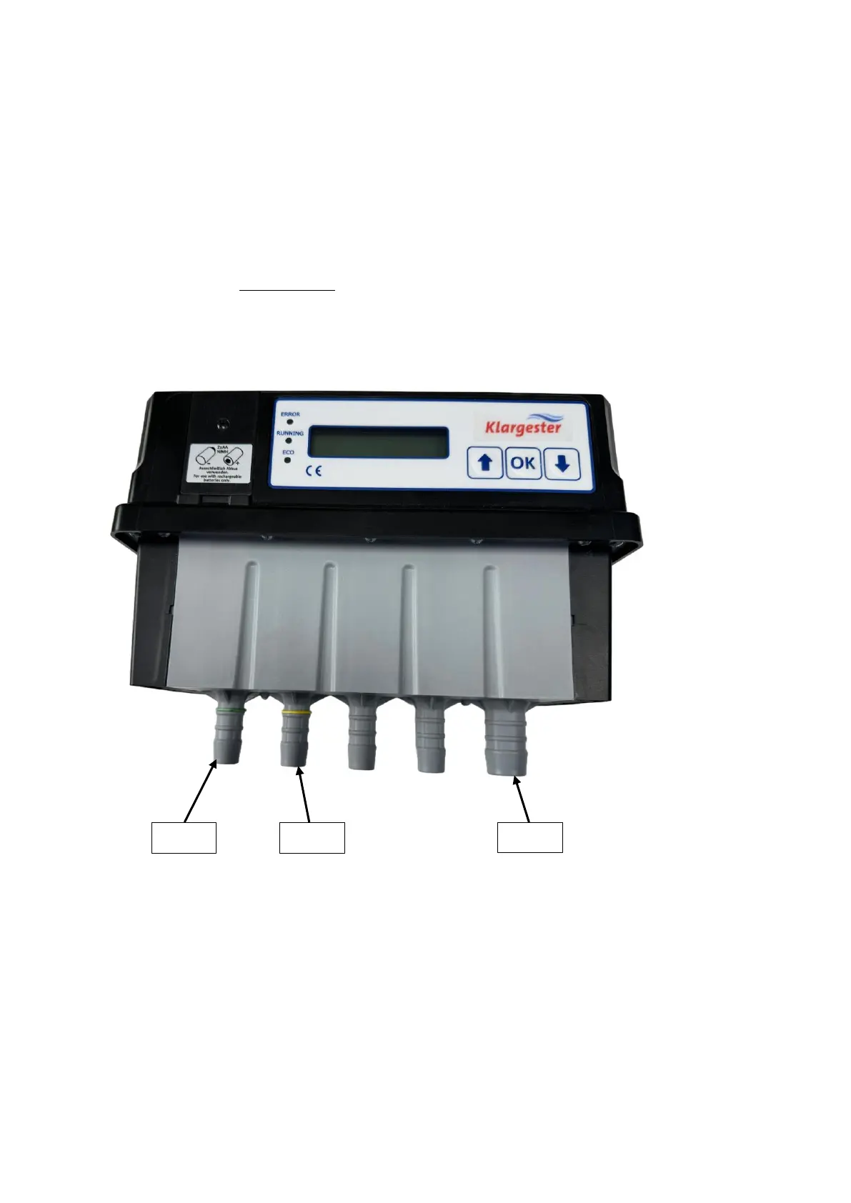
4.1 Valve Outputs
The valves are counted from le to right:
Valve 1 (1/2” Hose tail) : Diuser (Aeraon) – Green Band
Valve 2 (1/2” Hose tail): Airli (Clearwater removal) – Yellow Band
Valve 3 (3/4” Hose tail): Blower inlet
4.2 Digital Inputs
The panel contains two digital inputs
I. Digital input 1 (IN1 on PCB): Will be used for high-level alarm detection via a float
switch.
II. Digital input 2 (IN2 on PCB): Will be used to activate the submersible pump for
pumped outlet tank. As factory setting, the digital input is bridged (activated, closed)
by a wire, if the submersible pump shall be used instead, the bridge can simply be
removed / disconnected (=DI2 open / disconnected ).
III. Relay Output +5VDC (REL OUT on PCB): Volt free contact which can be used for low
voltage devices such as the panel beacon or for the SmartServ Pro.