PT8100 Service Manual
11
26 204-008000-R04A
Dustproof Strip between Top
and Bottom Al Case
2
27
203-008000-R01B
Al Bottom Case
1
28
301-30250D-R01
Screw M3*25
6
29
201-008100-R04A
Lens
1
30
202-008100-R01A
Rubber Key
1
31
203-008100-R01A
Metal Dome
1
32 202-008000-R03A
Heat Conductive Rubber
Cushion
1
33 202-008100-R02A
LCD Dustproof Rubber
Cushion
1
34
PCB Assembly
1
35
302-26060D-R01
Screw M2.6*6
3
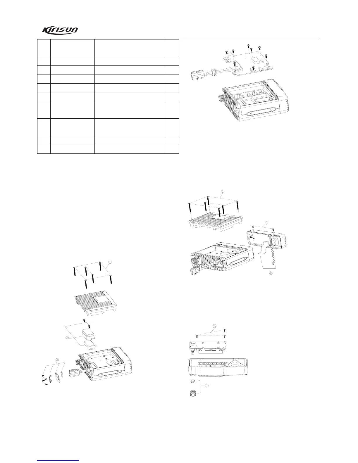
6.2 Instruction for Disassembly of the Radio for Maintenance
6.2.1 RF-PCB disassembly
① Screw off the six M3*25 screws on the Al bottom case, and
remove the Al bottom case (See figure below).
② Screw off the two screws for power module and then remove
the shield for power module. Then remove the solder of the
power module on the PCB with a soldering iron (See figure
below).
③ Screw off the four M2.5*5 screws on the baffle plate, and then
remove the metal baffle plate, the power cable fastener and the
rubber plug for external speaker jack (See figure below).
④ Remove the flat cable and the speaker wire, and then remove
the solder between the antenna connector and the RF-PCB with a
soldering iron. Screw off the screws, and take the RF-PCB out of
the top Al case carefully (See figure below).
6.2.2 Key-PCB disassembly
① Screw off the six M3*25 screws on the Al bottom case, and
remove the bottom case (See figure below).
② Remove the flat cable and speaker wire (See figure below).
③ Screw off the two M2.5*5 screws on the front cabinet, and
then separate the front cabinet from the main machine (See figure
below).
④ Pull out the volume knob, and then remove the circlip and nut
for volume knob (See figure below).
⑤ Screw off the three fixing screws (M2.6*6) for Key-PCB, and
then take the Key-PCB out of the plastic front cabinet (See figure
below).
After the disassembly above, you can repair and adjust the
radio according its actual malfunction.