PT8100 Service Manual
4
18 Momentary
Monitor / Call
Cancel
Press and hold the button, QT/DQT/2Tone/5Tone/DTMF
signaling will be closed. Release the button to return to
normal operation. Press the button during the Select Call
state, the radio will exit Select Call state.
19 Monitor/Call
Cancel
Press the button to close QT/DQT/2Tone/5Tone/DTMF
signaling, then you can receive signals that cannot be
received during normal operation. Press the button again
to resume normal operation. Press the button during the
Select Call state, the radio will exit Select Call state.
20 Momentary
Squelch Off /
Call Cancel
Press and hold the button to open squelch; release it to
resume normal operation.
Press it during the Select Call state, the radio will exit
Select Call state.
21 Squelch
Off/Call Cancel
Press the button to open squelch; press it again to resume
normal operation.
22 Emergency Press the button to make an alarm tone according to the
setting of the programming software or send your ID or
background sound to your partner or the system.
23 Call 1 Press to send the preset code.
24 Call 2 Press to send the preset code.
25 Call 3 Press to send the preset code.
26 Call 4 Press to send the preset code.
27 Menu
Select/Enter
Press to enter the Menu Mode, to make menu selections
and save.
28 Lone Worker Press to enable/disable Lone Worker function.
29 Scan List Edit This allows the radio-user to edit a Scan List. Scan List
editing is only available for Scan Lists where the User
Programmable field has been enabled.
30 Backlight Press to toggle between “Light”, “Dark” and “Auto” for
the backlight.
Chapter 4 Circuit Description
4.1 Frequency Configuration
ANT
ANT SW RF AMP
MCF
49.95MHz
IF SYSTEM
CF1
450KHz H
CF2
450KHz F
X3 multiply
AF AMP
TCXO
16.8MHz
MIC AMPPLL VCOTX AMPPA AMP
RX
TX
Figure 4.1 Frequency Configuration
The receiver adopts double mixing. The first IF is 49.95MHz
and the second IF is 450kHz.
The first local oscillator signal of the receiver is generated by
the frequency synthesizer and the second local oscillator signal is
generated by frequency tripler X1.
The transmitter signal is produced by the frequency
synthesizer.
The reference frequency of the frequency synthesizer is
provided by TCXO.
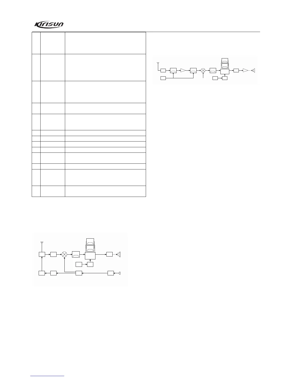
4.2 Principle of Receiver (RX)
MCF
49.95MHz
IF SYSTEM
CF1
450KHz H
CF2
450KHz F
X3 mult iply
AF AMP
TCXO
16.8MHz
NJM2902
BPF
RF AMP
BPF
ANT SW
ANT
IC11
MCU
1st Local OSC
D3 D11
Q18
Q19
IC4
IC9
IC9 TDA1519C
Figure 4.2 Principle of Receiver
Front end
The signal coming from the antenna passes through the
RX/TX switch circuit (D3 and D37), and passes through a BPF
consists of two LCs to remove unwanted out-of-band signals, and
then is routed to the low noise amplifier (LNA) consists of Q18
and its peripheral components where it is amplified.
Output signal from the LNA passes through a BPF consists of
three LCs to further remove unwanted out-of-band signal, and
then goes to the first mixer (Q19).
AGC circuit
AGC circuit, which consists of Q16 and its peripheral circuit,
will work to reduce the gain of Q18 only when the input signal is
too large.
First mixer
The Rx signal from LNA is mixed with the first local
oscillator signal from the frequency synthesizer to produce the
first IF signal (49.95MHz).
IF circuit
The first IF signal passes through the crystal filter (XF1) to
remove the adjacent channel signal and signal outside the
adjacent channel. Then the filtered signal is amplified by the first
IF amplifier (Q20), and is sent to the IF processing IC (IC6,
TA31136).
IF IC consists of the second mixer, IF amplifier, limiter,
discriminator, noise amplifier, and audio low pass filter.
Signal (16.8MHz) from X1 is multiple-amplified by Q11 and
its peripheral circuit to produce the second local oscillator signal.
Then the second local oscillator signal (50.4MHz) is mixed with
the first IF signal (49.95MHz) in IC6 to generate the second IF
signal (450kHz). And then the second IF signal is amplified and
limited in IC6, filtered by its ceramic filter (CF1 or CF2,
450kHz), and then demodulated in IC6. After that, the
demodulated signal is routed to the audio circuit to output audio
signal.
The selection circuit of the second IF filter consists of CF1,
CF2, D20, D21, and the peripheral circuit. When the mobile radio
is set to wideband, CF2 is put through and takes effect, while