PT8100 Service Manual
16
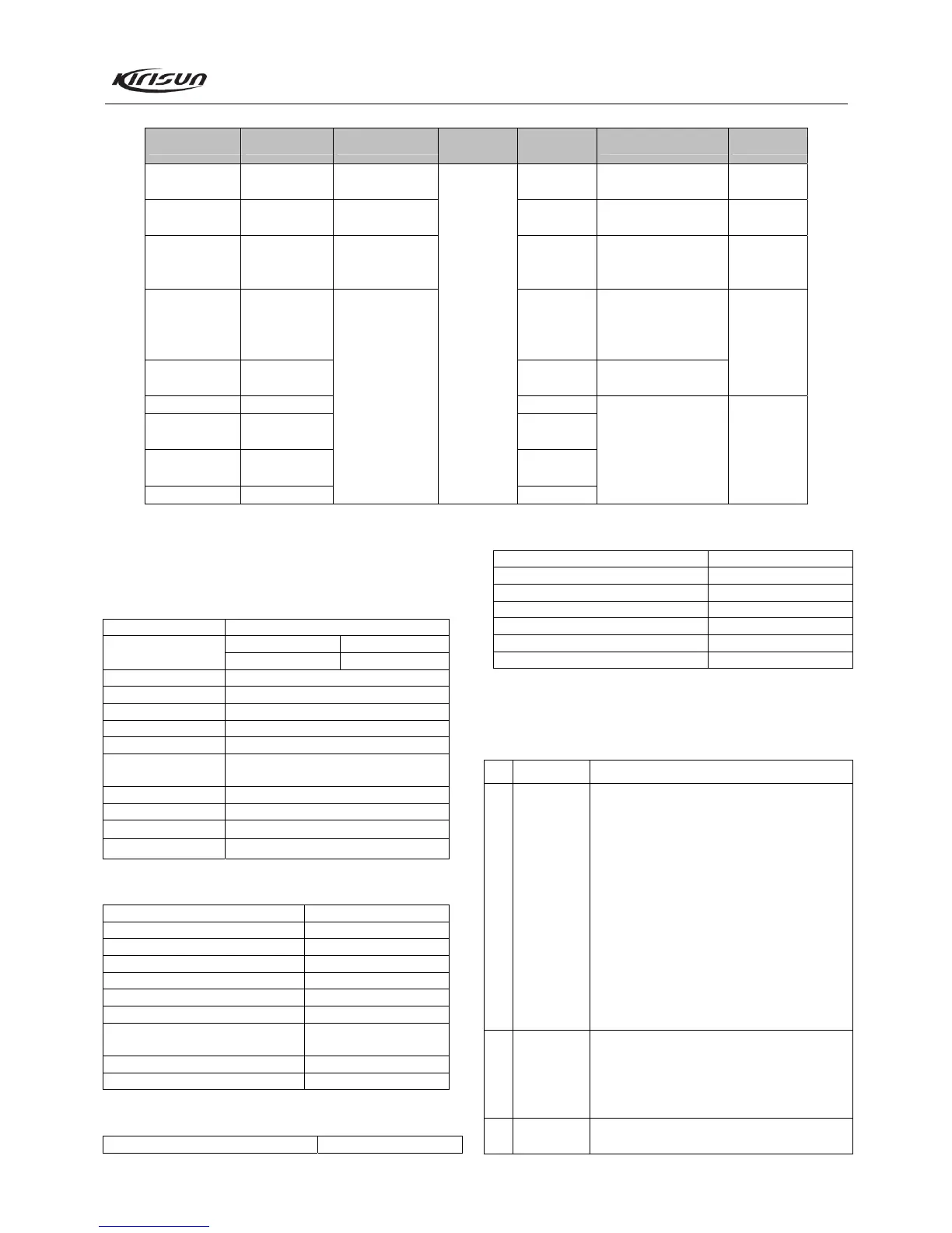
Table 7.5 Transmitter Section
Item Test Condition Test Equipment
Measurement
Terminal
Adjustment
Parts
Requirement Remark
Tx frequency
Frequency counter
/ General test set
Tuning mode Within ± 100Hz
DCS waveform
(balance)
Oscilloscope /
General test set
VR1
Smooth and similar to
square wave
Power
Power meter /
General test set
Ammeter
Tuning mode Adjust to 22W/5W
Max. modulation
DEV
CH: Tx low freq
point
AG:
1kHz/120mV
VR2
Adjust to ±
4.2kHz/2.1kHz
DTMF DEV Tuning mode
Adjust to
±3.5kHz/1.7kHz
± 200Hz
CTCSS DEV CTCSS: 67Hz Tuning mode
CTCSS DEV
CTCSS:
151.4Hz
Tuning mode
CTCSS DEV
CTCSS:
254.1Hz
Tuning mode
DCS DEV DCS: 023N
Deviation meter /
General test set
Antenna
Tuning mode
Adjust to ±
0.75kHz/0.35kHz
± 50Hz
Chapter 8 Specifications
8.1 General Specifications
Product Model PT8100
136-174MHz 400-450MHz Frequency
438-490MHz 350-400MHz
Type of Modulation 16KF3E/11KF3E
Number of Channels 256
Channel Spacing 25kHz/12.5kHz
IF 1
st
IF: 49.95MHz; 2
nd
IF: 450kHz
Operating Voltage 13.8V, cathode grounded
Operating
Temperature
-30℃~ +60℃
Antenna Impedance 50
MIC Impedance 2.2k
Dimension 150*43*131mm (radio only)
Weight 1070g (radio only)
8.2 RX Part
Usable Sensitivity (12dB SINAD) -118dBm
Squelch Open Sensitivity -121dBm @ SQL1
Rx Residual Output W: -45dB; N: -40dB
Modulation Rx Bandwidth W: ± 7kHz; N: ± 3.5kHz
Adjacent Channel Selectivity W: 70dB; N: 60dB
Intermodulation Rejection 65dB
Spurious Response Rejection 70dB
Audio Output Power 4W, balanced @
distortion 5%, 8
Rx Current Consumption 1A
Standby Current 100mA
8.3 TX Part
Tx Power 20W/5W @ 13.8V DC
Frequency Stability ± 2.5ppm
Max. Modulation Deviation ± 5kHz / ± 2.5kHz
Modulation Distortion (300-3000Hz) 3%
Adjacent Channel Tx Power W: 70dB; N 60dB
Spurious Emission 70dB
Residual FM W: -45dB; N: -40dB
Tx Current Consumption 7A @ 13.8V DC
Chapter 9 Troubleshooting
No. Problem Causes and Solutions
1 Power on
Failure
A. The power cable is not reliably connected
with the accumulator or the radio, please
reconnect it. Make sure the power voltage
should be larger than 13V.
B. The fuse of the power cable is burnt out.
Please change it.
C. The power button is in poor contact. Please
change the rubber key or change the key
PCB.
D. The accumulator is out of power. Please
charge it or change a new one.
E. The MCU is broken, please change the IC.
F. The zener diode IC17 is broken, please
change the IC.
2 PLL
unlocked
(Beeping)
A. The PLL crystal oscillator X1 is broken. Please
change it.
B. The oscillator transistor is broken. Please
change it.
D. The PLL IC3 is broken. Please change it.
3 Cannot
transmit
A. The frequencies of both users are not the
same. Please select the same frequency