PT8100 Service Manual
15
frequency as the adjusted frequency point and with the signal
level of -116dBm, audio frequency of 1kHz, and deviation of
1.5kHz to the antenna connector of the mobile radio), double
click “RSSI Level1”, and select “Narrowband”. Choose a
frequency point, and click “Begin”, the programming software
will adjust the value automatically. When the value keeps stable,
click “OK”, the adjustment is completed.
c. In the “Tuning Mode” (input RF signal with the same
frequency as the adjusted frequency point and with the signal
level of -80dBm, audio frequency of 1kHz, and deviation of
3kHz to the antenna connector of the mobile radio), double click
“RSSI Level4”, and select “Wideband”. Choose a frequency
point, and click “Begin”, the programming software will adjust
the value automatically. When the value keeps stable, click “OK”,
the adjustment of that frequency point is completed. Use the
method to adjust the five frequency points of “Lowest”, “Low”,
“Mid”, “High” and “Highest” respectively.
d. In the “Tuning Mode” (input RF signal with the same
frequency as the adjusted frequency point and with the signal
level of -80dBm, audio frequency of 1kHz, and deviation of
1.5kHz to the antenna connector of the mobile radio), double
click “RSSI Level4”, and select “Narrowband”. Choose a
frequency point, and click “Begin”, the programming software
will adjust the value automatically. When the value keeps stable,
click “OK”, the adjustment is completed.
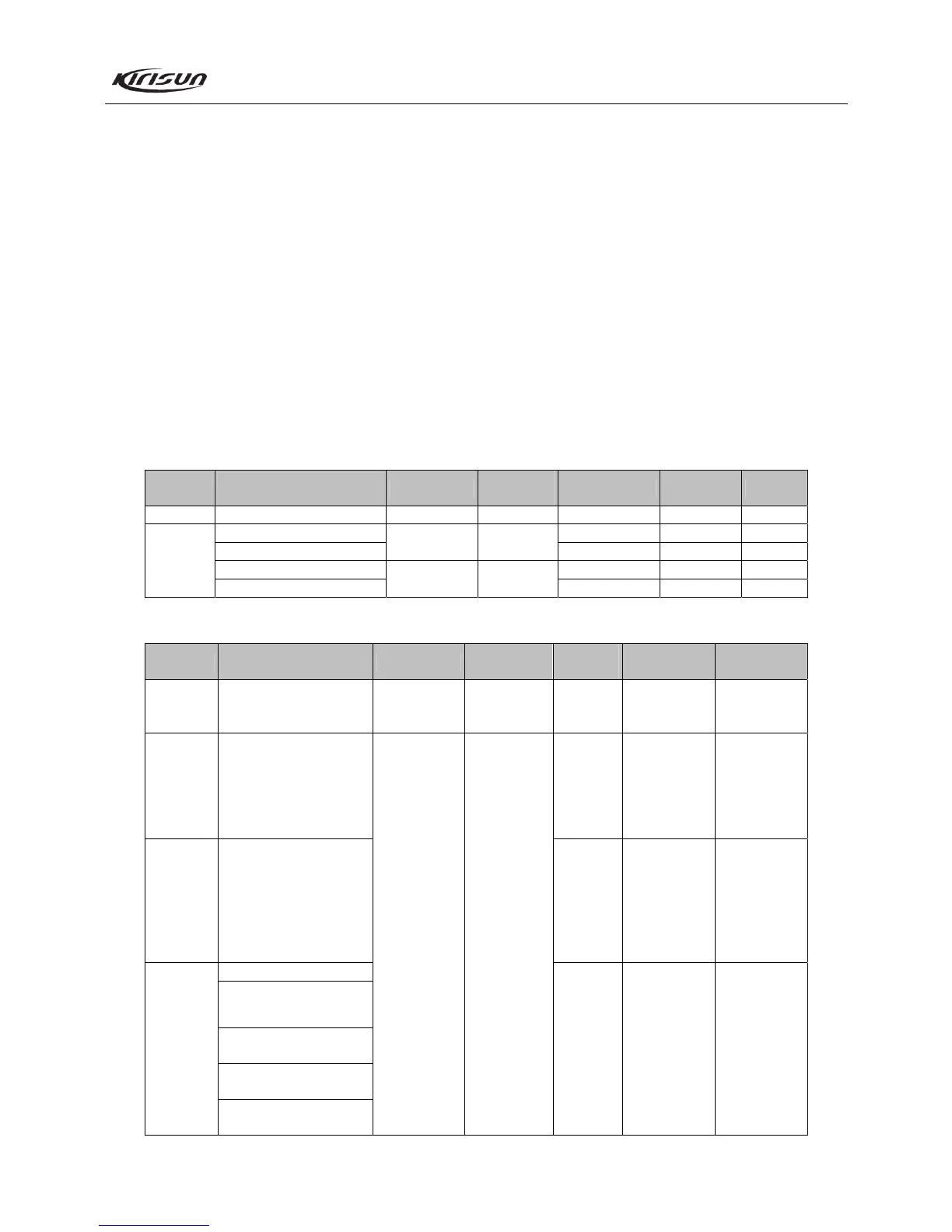
7.3 Adjustment Description
Refer to Table 7.3, 7.4, and 7.5 for the above mentioned
adjustment.
Table 7.3 VCO
Item Test Condition Test Equipment
Measurement
Terminal
Adjustment Parts Requirement Remark
Setting BATT terminal voltage: 13.8V DMM PD
CH: Rx high freq point C122 3.5V ± 0.3V Adjust
CH: Rx low freq point
﹥0.6V Observe
CH: Tx high freq point C39 3.5V ± 0.3V Adjust
VCO lock
voltage
CH: Tx low freq point
﹥0.6V Observe
Table 7.4 Receiver Section
Item Test Condition Test Equipment
Measurement
Terminal
Adjustment
Parts
Requirement Remark
BPF
Spectrum
analyzer /
General test set
Before mixing
Tuning
mode
Smooth wave
User
adjustment not
recommended
Audio
Power
Test freq: Mid freq point
Antenna connector input:
RF OUT: -47dBm (1V)
MOD: 1kHz
DEV: ± 3.0kHz/± 1.5kHz
Audio load: 8
Tuning
mode
(Turn the
volume knob
clockwise to
the end) Audio
power > 4W
Sensitivity
CH: Mid freq point
CH: Low freq point
CH: High freq point
RF OUT: -119dBm
(0.25V)
MOD: 1kHz
DEV: ± 3.0kHz/± 1.5kHz
Tuning
mode
SINAD: 12dB
or higher
CH: Rx mid freq point
SQL9 Open
RF OUT: -116dBm
SQL9 Close
RF OUT: -118dBm
SQL1 Open
RF OUT: -123dBm
Squelch
SQL1 Close
RF OUT: -125dBm
RF signal
generator
Oscilloscope
Audio
frequency
voltmeter
Distortion
meter
General test set
Speaker
connector
Tuning
mode
Normal squelch
open after
adjustment