PT8100 Service Manual
12
Chapter 7 Adjustment
Before test/adjustment, make sure all equipment has been
well grounded!
Before test/adjustment, make sure the antenna output terminal
has been correctly connected to corresponding equipment or
load!
The transmitter output terminal must be terminated with an
RF power attenuator and connected to a standard signal generator
(SSG)/frequency counter/deviation meter/spectrum analyzer!
Make sure no transmission operation is being conducted
while measuring the receiver!
During the adjustment/test/maintenance, make sure reliable
anti-static measures are taken for human body and equipment.
7.1 Equipment and Software Required for Test and
Adjustment
Equipment and software listed in Table 7.1 are required for
test and adjustment of PT8100.
Table 7.1 Equipment and Software Required for Test and
Adjustment
No. Item Specifications
1 Computer
P2 or above, IBM compatible PC, WINDOWS
98/ME/2000/XP Operating System
2
Programming
software
KSP8100
3
Programming
cable
KSPL05
4 Clone cable KCL02
5
DC regulated
power supply
Output voltage: 13.8V
Output current: 20A
6 RF power meter
Measurement range: 0.5-50W
Frequency range: 100MHz-500MHz
Impedance: 50
SWR 1.2
7
Frequency
counter
Frequency range: 0.1 - 600MHz
Frequency accuracy: better than ±1×10
-6
Sensitivity: better than 100mV
8 Deviation meter
Frequency range: DC - 600MHz
Measurement range: 0 - ±5kHz
9 DMM
Input impedance: above 10M/V DC, capable of
measuring voltage, current and resistance.
10
Audio signal
generator
Frequency range:2-3000Hz
Output level: 1-500mV
11
RF power
attenuator
Attenuation: 40dB or 50dB
Supporting power : higher than 50W
12
Standard signal
generator
Frequency range: 10MHz-1000MHz
Output level: 0.1uV-32mV (-127dBm~-17dBm)
13 Oscilloscope
Frequency range: DC~20MHz
Test range: 10mV-20V
14
Audio frequency
voltmeter
Test range: 10mV-10V
Recommendation: Item 6, 7, 8, 10, 11, and 12 listed in the
table can be replaced by HP8920 general test set.
81
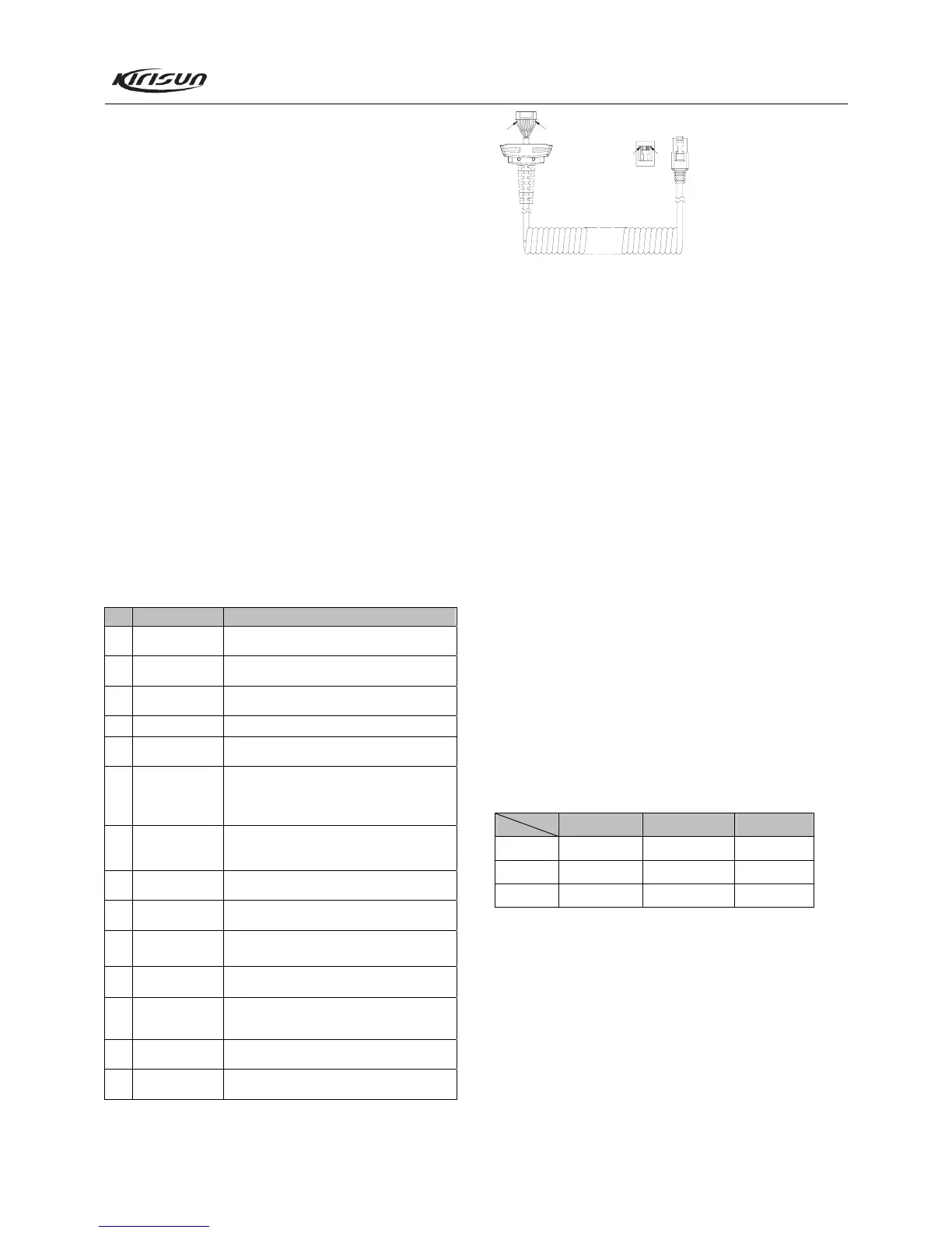
1
2
3
4
8
5
7
6
18
(PTT)
(MBL)
(PSB)
(GND)
(HOOK)
(ME)
(MIC)
(CM)
Figure 7.1 External Microphone Interface Definition
7.2 Adjustment
After changing components during the maintenance, it is
necessary to test the radio and adjust its technical parameters. The
following part is going to introduce the adjustment items.
Some parameters can be adjusted by use of KSP8100
programming software (in the Tuning Mode). The adjustable
parameters are as follows:
7.2.1 VCO
a. Adjust the channel to its high frequency point (See Table 7.2).
b. Under the receiving status, measure the voltage of PD by
DMM. Then adjust the PD voltage to be 3.5V ± 0.3V by tuning
the trimming capacitor C122.
c. Under the transmitting status, measure the voltage of PD by
DMM. Then adjust the PD voltage to be 3.5V ± 0.3V by tuning
the trimming capacitor C39.
d. Adjust the channel to its low frequency point (See Table 7.2).
e. Under the receiving status, measure the voltage of PD by
DMM, the value should be larger than 0.6V.
f. Under the transmitting status, measure the voltage of PD by
DMM, the value should be larger than 0.6V.
Table 7.2 High/Center/Low Frequency Point for PT8100
Low Freq Point Center Freq Point High Freq Point
PT8100-01 136.125MHz 154.125MHz 173.975MHz
PT8100-02 400.125MHz 425.125MHz 449.975MHz
PT8100-03 438.125 MHz 464.125 MHz 489.975MHz
7.2.2 Tx deviation (set the HP8920 to be in the Tx status, and set
the filter to be 50Hz~15kHz)
a. Input audio signal of 120mV, 1000Hz to the MIC jack of the
radio.
b. Set the channel to its low frequency point (See Table 7.2).
c. Press and hold the PTT key while adjusting VR2 to make the
deviation be 4.2kHz.
d. Observe the deviation of other channels, which should be
larger than 3.5kHz.