PT8100 Service Manual
10
Connect the radio to the serial port of the computer with the
special programming cable. Refer to Figure 5.1.
Warning: Before entering the PC Test Mode, please firstly
connect a 50 HF load to the antenna connector of the radio or
connect the radio to a general test set.
With the KSP8100 programming software, you can enter the
Tuning Mode under PC Test Mode to tune the following
parameters of the radio:
1) Frequency
2) Low/Mid/High power
3) Tone Deviation
4) DTMF Deviation
5) DCS Balance
6) DCS Deviation
7) CTCSS (67) Deviation
8) CTCSS (151.4) Deviation
9) CTCSS (254.1) Deviation
10) Rx Sensitivity
11) SQL9/SQL1 On
12) SQL9/SQL1 Off
13) RSSI Level1/Level4
5.3 Firmware Programming Mode
The radio is equipped with an internal Flash ROM which can
be upgraded when new features are released. The operation
procedures are as follows:
1. Turn the radio power ON and the radio enters User Mode.
2. Run the firmware programming software KMU on PC.
3. Connect the radio to the computer by the programming cable.
4. Select a COM port and proper baud rate (115200 is
recommended) according to the actual situation. Then click on
“E.P” to start downloading. The LCD will display “Firmware”.
5. After the communication ends successfully, click on “OK” to
exit.
6. If you want to continue programming other radios, repeat steps
1 to 5.
Chapter 6 Disassembly and Assembly for
Maintenance
The radio is a kind of sophisticated communication
equipment with precise structure and small size. You should
assemble and disassemble it carefully during the maintenance.
The instructions for the assembly and disassembly are as follows.
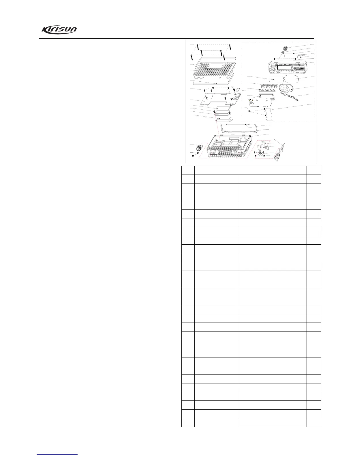
6.1 Exploded View
33
32
35
31
34
30
29
8
9
10
11
6
7
5
2
3
4
1
23
面壳组件装配
28
27
16
17
18
19
20
21
22
24
25
15
14
13
12
6
19
19
26
26
No. Part No. Description PCS
1
201-008100-R02A
Volume Knob
1
2
203-007200-R08
Nut for Knob
1
3
204-008200-R08A
LCD Protective Film
1
4
LOGO
1
5
201-008100-R05A
Light Guide
1
6
301-25050J-R01C
Screw M2.5*5
6
7
201-008100-R01A
Front Cabinet
1
8
204-008000-R01A
Dustproof Net for Speaker
1
9
121-100000-R19
Speaker
1
10
120-400000-R14
Speaker Wire
1
11
120-400000-R15
Flat Cable
1
12 204-008000-R02A
Upper Dustproof Strip for
Front Cabinet
1
13 204-008000-R03A
Lower Dustproof Strip for
Front Cabinet
1
14
203-008000-R02B
Al Top Case
1
15
120-100000-R42A
Power Cable
1
16
201-008100-R03A
Power Cable Fastener
1
17
203-008000-R03A
Metal Baffle Plate
1
18 202-008200-R02A
Rubber Plug for External
Speaker Jack
1
19 303-30100G-R01
Screw M3*10, with Spring
Washer
5
20
203-008200-R03B
Antenna Connector
1
21
102-304452-R01
Power Module
1
22
203-008200-R05A
Shield for Power Module
1
23
204-008200-R10B
Electric Conductive Sponge
1
24
Main Board Assembly
1
25
301-30060G-R01
Screw M3*6
7
Front Cabinet Assembly