3 of 12 2011-9-23
First of all, please check whether there is a hole for the power cable on the insulating board. If no,
please bore the board with the suitable drill bit and fix a rubber grommet on it.
Afterwards, please have the cable pass through the insulating board and lead from the car into the
car engine. Connect the red conductor to the positive terminal of the accumulator and the black
conductor to the negative terminal.
At last, ring the remained conductor and fix it.
Note: Please maintain the sufficient relaxation of the power cable to make it convenient to dismantle
the radio in the state of power connection.
1.22 Radio Installing
Warning: For passengers’ safety, please fix the radio firmly on the fixed bracket so that the radio will
not be loosened in case of collision.
1) The fixed bracket is taken as an example. Draw the position and drill a hole on the instrument
panel first, and then install the fixed bracket with 4 M5*16 self-tapping screws. (Note: please fix
the radio at the position convenient for operation and control, and leave an enough space for
fixation and connection of the cable.)
2) Slide the radio into the fixed bracket and fix it with 4 M4*10 combination screws (plus plain
washer and spring washer). (Different combinations of fixing holes are selectable to adjust the
radio to the proper height and visual angle.)
3) Connect the antenna and the power cable to the radio.
4) Install the microphone hanger at the position easy to use, with 2 M4*16 self-tapping screws.
(The microphone and its cable should be fixed at the position not affecting safe driving.)
5) Connect the microphone to the microphone jack on the front panel of the radio and put it on the
hanger.
Note: When replacing the protective tube for the power cable, please use the one of the same
specification without fail. It is not allowed to change it into the tube of higher capacity.
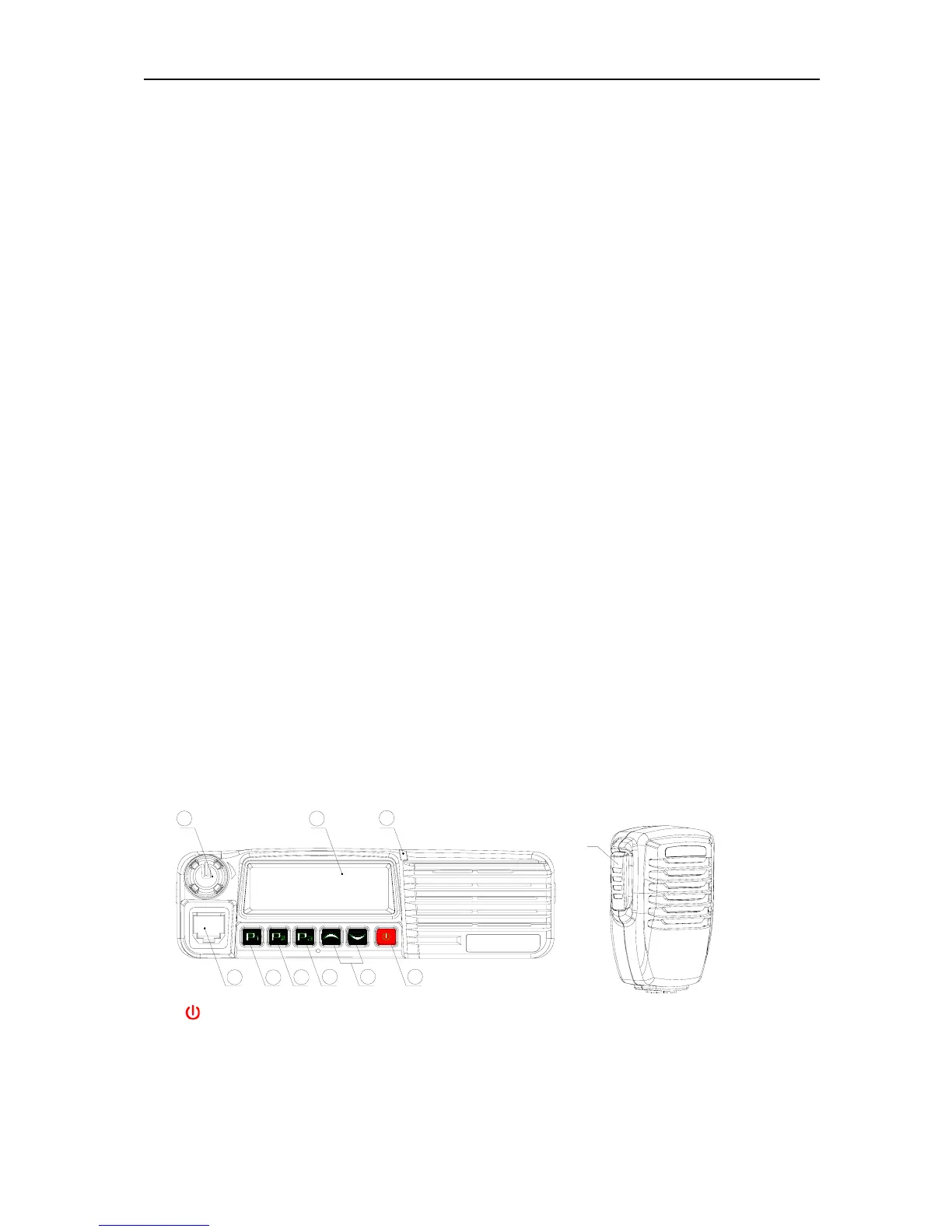
2.Radio Overview
2.1 Description of External View
1
2
3
4
5
6
7
8
9
⑾
(1)
power button
Press this button for a long time (more than 1.5 seconds) to switch the radio on/off.
(2)LED indicator
The red indicator will light while transmitting; the green indicator will light when it receives the
carrier.
The led flashes orange on received correct DTMF/2Tone signaling.
The red indicator flashes in the scanning process.